


12/03/15
Overview
The oxygen supply system supplies oxygen to the crew circuit.
Smoke goggles are parts of the system and give smoke protection.
Oxygen is contained in the cylinder at high pressure (an optional oxygen cylinder is available for long distance flights). The regulator decreases high pressure oxygen to a lower pressure for the use with passengers, therapeutic needs, and crew masks. The cylinder regulator includes safety relief valves (on the high-pressure and reduced-pressure lines) which are connected to an overboard discharge line and indicator.
Oxygen is supplied by the electro-pneumatic actuating valve (EPAV) to the oro-nasal quick-donning masks through low-pressure lines. The interface between the crew masks and the oxygen supply lines are quick-disconnects. Smoke goggles are provided for smoke protection. The smoke goggles are used in conjunction with the quick donning masks.
A pressure and temperature transducer is in the rear part of the center fuselage above the 77 cu.ft. oxygen cylinder. It gives the ambient temperature of the oxygen storage cylinder and the oxygen pressure in the cylinders to the EPAV. From these two signals, the EPAV gives a temperature-compensated pressure signal and sends it to the EICAS. The EICAS converts the temperature-compensated pressure signal into liters of oxygen for display of oxygen quantity in the cockpit, in relation to the numbers of cylinders on the aircraft.
The cylinders (one baseline and one optional for long distance flights) are refilled through the oxygen service panel external to the aircraft through the filler valve and the filling line. The filler valve includes a check valve, filter, and flow restrictor to prevent an oxygen overpressure condition during refilling. The high-pressure gauge in the panel shows the oxygen cylinder pressure during refill.

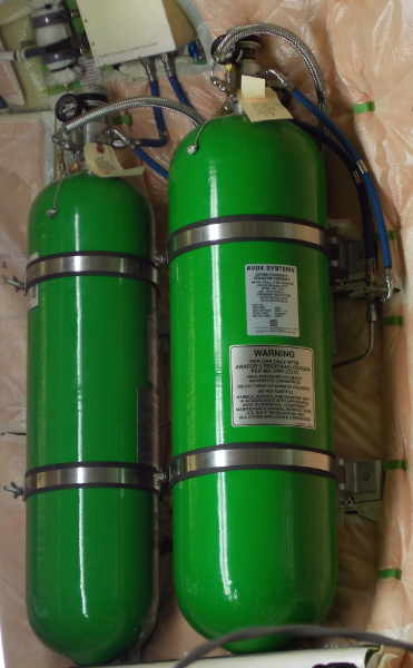
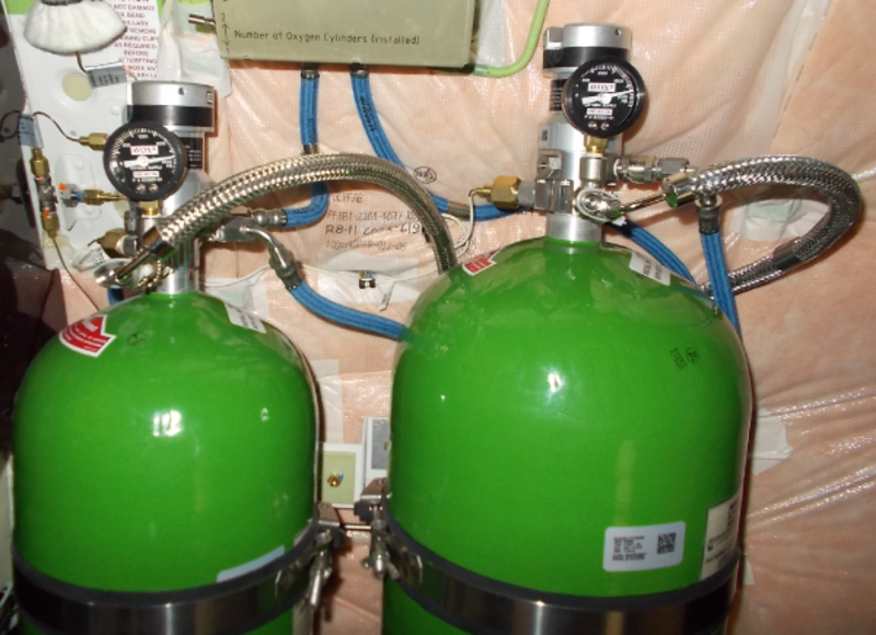
Oxygen Storage Cylinder (77 cu. ft) and Regulator
The 77 cu. ft cylinder is in a dedicated compartment in the lavatory section on the right side of the aircraft. The cylinder is attached to the aircraft structure with two cylinder band clamp brackets. The oxygen storage cylinder is made of aluminum and Kevlar composite material. It has a pressure-reducing regulator with a pressure gauge on its top. The cylinder holds the oxygen gas, which is at a nominal pressure of 1,850 psi (12,755 KPa).
The pressure-reducing regulator is manually operated by an oxygen shutoff valve toggle safety wired in the ON position. It has one inlet with a self-venting device (the cylinder refill port), two high-pressure outlets (the indication outlet and safety relief) and two low-pressure outlets (supply of oxygen and safety relief). The safety relief valves are connected through the discharge lines to an overboard discharge indicator near the servicing panel.
When the toggle is in the ON position, the regulator supplies low-pressure oxygen (60 to 80 psi) to the EPAV via its low-pressure outlet. The EPAV supplies and optimizes oxygen flow to the crew masks, passenger drop-out boxes and therapeutic masks. When the toggle is in the OFF position, oxygen is not available to the low-pressure outlets. High-pressure oxygen remains available at the high pressure outlets.


Oxygen Storage Cylinder (115 cu. ft) and Regulator
The optional 115 cu. ft oxygen storage cylinder is for long distance flights. The cylinder is in the oxygen compartment adjacent to the 77cu. ft oxygen storage cylinder. It has the same functions and is equipped with the same type of pressure-reducing regulator.
03/11/16
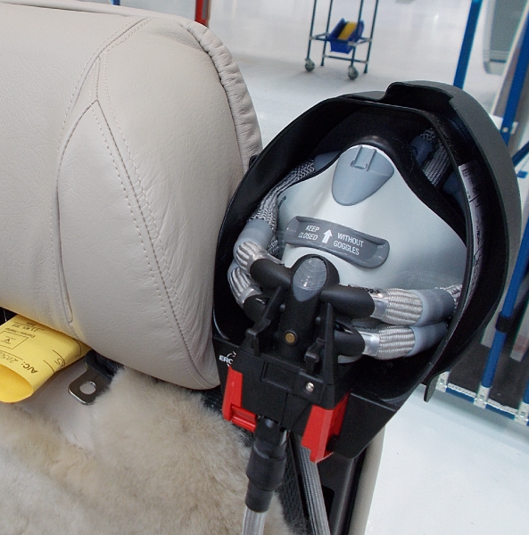
Crew Oxygen Mask
The quick-donning crew oxygen mask includes:
- An oro-nasal face piece, with a face seal and a self extinguishing plastic shell. The face piece has a venting system on the bridge of the facepiece. The venting system opens automatically when smoke goggles are put on the face of the pilot.
- A built-in oxygen mask regulator, which has a “PRESS-TO-TEST”, NORMAL, 100%, “EMERGENCY” control knob.
- An inflatable harness, which has a non-flammable braid.
- A microphone.
- An oxygen supply hose, which has an in-line flow indicator and a radio cord assembly.
- A COMFORT BUTTON which is used to inflate or deflate the harness.
The oxygen is supplied to the crew oxygen mask by the oxygen supply hose at a pressure of 60 to 85 psi. The crew oxygen masks are installed in the cups.
Post Customer Option C25-620 - The jump seat oxygen mask is installed in a storage box behind the co-pilot.


12/03/15
Stowage Cup
The stowage cups supply stowage for the crew oxygen mask. They are on each of the crew seats. Each cup is on a bracket on the outboard side of the head rest. The cups include a label for operating instructions to release the crew mask and for its stowage.

Oxygen Outlet
There are two oxygen outlets which are quick disconnect couplings. The couplings are on the lateral consoles of the cockpit. The couplings are bayonet-type, self-sealing outlets. When connected to the outlet, the check valve is lifted automatically off its seat and the oxygen flows to the mask.


Oxygen Content Indication System
The oxygen content indication system gives indication of the status of the oxygen system.
Oxygen Pressure/Temperature Transducer
The pressure/temperature transducer measures the cylinder pressure and ambient temperature of the oxygen compartment. The transducer sends temperature and pressure signals to the electro pneumatic actuating valve (EPAV) which calculates a new pressure signal that agrees with standard temperature of 70°F (21°C). The information is then sent to the engine indicating and crew alerting system (EICAS). The transducer is supplied 28 VDC from the R ESS BUS.

Overboard Discharge Indicator
The oxygen discharge indicator gives a visual indication of oxygen venting overboard which can be seen during a preflight walkaround or other ground checks. The indicator is on the aircraft external surface above the oxygen service panel and is connected to the high- and low-pressure oxygen lines. It has a mounting flange and inlet fitting, and a green nylon disc held in place with a retaining ring.

06/06/16
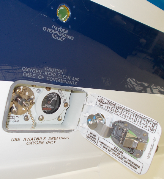
Oxygen Fill System
The oxygen fill system provides the ability to refill the oxygen storage system externally without removing the cylinder(s) from the aircraft. The servicing panel is on the right side of the rear fuselage. The cylinders are attached to the structure with cylinder brackets in a dedicated compartment in the lavatory. The location of the servicing panel is not near other aircraft services. This is to supply protection to the oxygen fill system from contamination.
Warning:
Obey all the oxygen safety precautions when you do maintenance on the oxygen system and oxygen system components. If you do not obey the safety precautions, you can cause a fire or an explosion. This can cause injury to persons and damage to equipment.
Oxygen Pressure Gauge
The oxygen pressure gauge is installed in the oxygen service panel behind the oxygen service door on the skin of the fuselage. The oxygen pressure gauge is installed next to the oxygen filler valve. It is connected to the oxygen storage cylinder(s) independently of the oxygen filler valve.
The oxygen pressure gauge shows the pressure in the oxygen storage cylinder(s).
Caution:
Make sure that the pressure of an oxygen cylinder is not less than 5 psi (34.47 kpa). If the pressure is less than 5 psi (34.47 kpa), contamination can go into the oxygen cylinder. If this occurs, you must send the oxygen cylinder to the manufacturer or an approved service center to be purged.
Oxygen Filler Valve
The oxygen filler valve is installed in the oxygen service panel behind the oxygen service door on the skin of the fuselage. The oxygen filler valve is installed next to the oxygen pressure gauge. The oxygen filler valve contains a check valve that only allows flow into the oxygen storage cylinder(s). The oxygen filler valve also contains a filter and a flow restrictor. The flow restrictor sets a limit on the rate at which the oxygen storage cylinder(s) can be filled. If oxygen flows into the system too fast, excessive heat can be produced. If too much heat is produced, a fire or explosion can injure persons or damage equipment.
Caution:
Make sure that the oxygen system pressure is not more than 1,850 psi (12,755 kpa) at 70 °F (21 °C). If the oxygen system pressure is more, it can cause damage to the system.

12/03/15
Operation
Oxygen Supply System
The oxygen is supplied to the crew oxygen mask by the oxygen supply hose at a pressure of 60 to 85 psi.
The crew masks provide and regulate oxygen to the crew. The pilot or copilot extracts the crew oxygen mask from stowage in case of emergency. The pilot or the copilot depresses the red toggles to inflate the pneumatic harness. When the harness is inflated, it has the diameter and rigidity to be fitted over the head. The pilot or copilot installs the mask on his face and releases the control plates. The harness deflates and closes around the user’s head holding the mask firmly against the face. The goggles are worn over the vent lever of the crew oxygen mask, which supplies vent air to the inner side of the goggles.
Operating Modes
There are three operating modes: normal, 100%, and emergency. The oxygen is supplied to the crew oxygen mask at a pressure of 60 to 85 psi.
- Normal—The crew oxygen mask provides a dilution of oxygen and air
- 100%—The crew oxygen mask provides pure 100% oxygen
- Emergency—The crew oxygen mask provides a constant flow of pure oxygen with a small amount of overpressure
Oxygen Content Indication System
The pressure/temperature transducer gives the ambient temperature of the oxygen compartment and the oxygen pressure in the cylinders to the EPAV. From these two signals, the EPAV calculates a temperature-compensated pressure signal and sends it to the data concentrator unit (DCU). The DCU converts the temperature-compensated pressure signal into liters of oxygen for display of the oxygen quantity on the EICAS, in relation to the numbers of cylinders installed on the aircraft.
When pressure in the tubing reaches a specified level, 105 psi ± 55 psi (723.95 kPa ± 379.21 kPa), the green snap-in disk of the overboard discharge indicator dislodges, giving a visual indication of the oxygen system venting. The disk does not seal tightly against the venting port. This allows pressure build-up from minor leakage to escape without dislodging the disk. Indication of excessive oxygen pressure venting to overboard is provided for all circumstances.
A pressure switch provides a signal to the DCU when the therapeutic circuit is on. The DCU then turns on the white ON label of the THERAPEUTIC pushbutton annunciator (PBA) on the OXYGEN control-panel.
The OXYGEN QUANTITY LOW message shows when the oxygen quantity is at the minimum level required for aircraft dispatch.
The OXYGEN VALVE CLOSED message shows when the oxygen cylinder shutoff valves (SOVs) are closed.
The PAX OXYGEN AUTO FAIL message shows when an error occurs in the AUTO mode operation. This message informs the pilots that DEPLOY should be set on the OXYGEN control-panel rotary switch. This message does not show if OFF is set on the OXYGEN control-panel, or if cabin altitude is less than 15,000 ft (4,572 m).
The EICAS messages that follows are related to the oxygen contents indication-system:
| EICAS MESSAGE(S) | LEVEL (COLOR) |
|---|---|
| OXYGEN QUANTITY LOW | CAUTION (amber) |
| OXYGEN VALVE CLOSED | CAUTION (amber) |
| PAX OXYGEN AUTO FAIL | CAUTION (amber) |


Oxygen Fill System
To fill the cylinder(s), remove the dust cap from the oxygen filler valve and connect a source of aviation breathing oxygen The oxygen flows to the oxygen storage cylinder(s) while the oxygen source has a higher pressure than the cylinder(s). The oxygen storage cylinder(s) must be filled to the pressure shown on the servicing chart on the door of the oxygen service panel for the ambient air temperature.
The pressure shown for a full cylinder(s) must be the same as the pressure on the servicing chart for the ambient air temperature. The chart is on the door of the oxygen service panel. The difference between the pressure on the servicing chart and the pressure on the oxygen pressure gauge must not be more than 150 psi. The oxygen pressure gauge must be monitored during refill of the oxygen storage cylinder(s). Pressure in the oxygen storage cylinder(s) must not go higher than the pressure shown on the servicing chart for the current outside air temperature.
After the oxygen storage cylinder is filled, the oxygen source is disconnected from the oxygen filler valve and the dust cap is installed. Make sure that the shutoff valve on all oxygen storage cylinders is safety wired in the ON position. If the shutoff valve is closed, there is no oxygen in the oxygen system. This can cause injury to persons.
Do not fill the oxygen system too fast or injury to persons or damage to equipment can occur. If the flow rate of the oxygen is too fast, heat can build up in the fill system tubing. Too much heat in the fill system tubing can cause a fire or explosion that can cause injury persons or damage equipment.
The oxygen service panel must be kept clean. Dirt can cause contamination of the oxygen system and can cause injury to persons or damage to equipment. The dust cap must be tightly connected to the oxygen filler valve or the oxygen system can become contaminated.
The oxygen service door must be tightly latched or the aircraft can be damaged in flight and cause injury to persons.
Caution:
Make sure that you put a protective cover or cap in all the open oxygen lines and component fittings. If you do not do this immediately after they are disconnected, unwanted materials can go into the oxygen system. This can cause contamination of the oxygen system.
12/03/15
System Interface
The oxygen supply system interfaces with the systems/components that follow:
- Overboard Discharge Indicator
- Oxygen Fill System
- Electro-Pneumatic Actuating Valve (EPAV)
The oxygen indication system has interfaces with the components/systems that follow:
- Oxygen Storage Cylinder (77 cu. ft.) and Regulator
- Oxygen Storage Cylinder (115 cu. ft.) and Regulator
- Electro-Pneumatic Actuating Valve (EPAV)
- Engine Indication and Crew Alerting System (EICAS)
- Crew Oxygen System
- Passenger Oxygen System
The oxygen fill system has interfaces with the component(s) and system that follow:
- Oxygen Storage Cylinder (77 cu. ft. or 115 cu. ft.) and regulator
- Engine Indication and Crew Alerting System (EICAS)
03/31/16
Training Information Points
Warning:
Obey all the oxygen safety precautions when you do maintenance on the oxygen system and oxygen system components. If you do not obey the safety precautions, you can cause a fire or an explosion. This can cause injury to persons and damage to equipment.
Warning:
When you do maintenance on the oxygen system, make sure that the tools and parts that you use are free from contamination. Tools and parts that are not sufficiently clean can cause an explosion or fire. This can cause injury or death.
10/22/20
Component Location Index
| Component Location Index | |||
|---|---|---|---|
| IDENT | DESCRIPTION | LOCATION | IPC REF |
| - | OXYGEN STORAGE CYLINDER (77 CU. FT.) AND REGULATOR |
FS602.20 | 35-11-01 |
| - | OXYGEN STORAGE CYLINDER (115 CU. FT.) AND REGULATOR |
FS602.20 | 35-11-05 |
| - | CREW OXYGEN MASK | ZONE(S) 211/212 | 35-11-07 |
| - | STOWAGE CUP | ZONE(S) 211/212 | 35-11-09 |
| - | OXYGEN OUTLET | ZONE(S) 211/212 | 35-11-13 |