


Overview
The maintenance diagnostic system operates as part of the integrated-avionics processor system (IAPS) to monitor diagnostic data from line-replaceable units (LRUs). The maintenance diagnostic system records a fail condition when it occurs. The recorded data helps personnel do troubleshooting procedures to find the defective LRU. The maintenance diagnostic system can also show rigging and test procedures for the applicable LRUs. Data supplied by the maintenance diagnostic system is displayed on the copilot multifunction display (MFD). The maintenance diagnostic system can download the fault data to a data loader. The system can also be connected to an external terminal.
03/30/22
Maintenance Diagnostic Computer (MDC)
The maintenance diagnostic computer (MDC) is the primary component of the maintenance diagnostic system.
The MDC is installed in the IAPS card cage. It includes a microprocessor and supplies data storage and interface functions.
The MDC examines and records the diagnostic data from the LRUs. Most LRUs do a self-test and send fail condition data to the MDC. The MDC receives a maintenance report for each sensed LRU and keeps it in nonvolatile memory (NVM).
The personnel can get access to the troubleshooting data from the MDC. The MDC keeps a file of fault conditions that occurred in real time and in previous time. The MDC can show time, date, and the aircraft identification. The MDC also supplies test and rigging procedures for applicable LRUs.
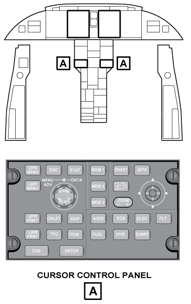
The CCP 1 or CCP 2 changes the pilot or the copilot MFD from its usual display mode to the maintenance diagnostic display-mode. The CCP 1 or CCP 2 controls the different diagnostic displays that show on the on-side displays.
The maintenance diagnostic system can download fault data to a USB memory stick in the data loader through FSU based MDC upload/download facility. The maintenance diagnostic system also supplies, through an RS-422 data bus, a remote data access (RDA) port. The RDA port is installed in the maintenance panel, in the LH equipment rack. This port is used to connect a portable maintenance-access terminal (PMAT) (Option).


Operation
The MDC collects faults data from the aircraft systems and shows the maintenance data on the pilot /copilot MFD or supplies the data to an external terminal. Fault data are received through the IAPS input/output concentrators (IOCs). Some fault data are received directly from the LRUs, and other fault data are received through reports sent by the LRUs to the data concentrator unit (DCU).
The MDC generates, formats, and transmits data collected to the MFD for the functions that follow: LRU diagnostics, LRU status, flight leg data, configuration-strapping unit data, clock and aircraft identity set operations, and disk operations.
The request for the MDC to transmit diagnostic data is done through the CCP. The MDC uses data from the configuration strapping unit (CSU) to know which LRUs are installed on the aircraft. The MDC finds which LRUs have fault conditions with the use of fault equations that are defined in MDC tables. In addition to the data that it collects from the LRUs, the MDC also receives (through the IOCs) messages from the DCU. The inputs from the DCU include identification labels related to the fail conditions of aircraft systems.
The messages supplied by the MDC are identified as fault messages or services messages in relation to the MDC tables data. Fault messages identify LRU fail conditions that need to be corrected as soon as possible by the maintenance personnel. Service messages identify conditions where some type of maintenance is necessary, but the LRU itself has no fail condition.
Processing of all LRU fault equations starts one minute after MDC power-up. The MDC processes those equations which have inputs that have changed since the last processing. The MDC tries to process all changes in one second. When many fault reports occur almost at the same time (burst conditions), the MDC tries to process all the LRUs that have fail conditions in three seconds. Current LRU diagnostic/status data and the MDC fault-equation tables fix the diagnostics results.
Evaluation of these equations supplies the LRU status and applicable fault messages and/or service messages.
12/19/15
Control and Displays
MDC Controls
To show the Maintenance Main Menu page, the personnel must push, at the same time, the A/ICE, ECS, and FUEL pushbuttons on the CCP. The Maintenance Main Menu page shows on the copilot MFD. The CCP pushbuttons and the joystick positions are used to control the copilot MFD, when the MFD is in the maintenance diagnostic mode.
The CCP controls are used for the primary MDC functions that follow:
- CKLST pushbutton, to get access to the CHECKLIST INDEX page
- ENTER pushbutton, to do the selection of an item on a maintenance page
- LWR FRMT pushbutton, to go back to the MAINTENANCE MAIN MENU page (from a maintenance page other than the MAINTENANCE MAIN MENU PAGE)
- JOY-UP position, to move the cursor up or increase a value
- JOY-DOWN position, to move the cursor down or decrease a value
- JOY-LEFT position, to move to the previous page, toggle between left and right, or move the cursor left
- JOY-RIGHT position, to move to the next page, toggle between left and right, or move the cursor right
- TR/WX pushbutton, to return to previous menu
- SKIP pushbutton, to move cursor between two parts on the same page
- TFC pushbutton, to exit the maintenance mode
More specific instructions on how to control the MFD with the CCP are shown on the applicable maintenance page. The primary controls are shown on a mode instruction column, on the left side of each maintenance page. This mode instruction column includes items that are shown as KEY/FUNCTION pairs. The KEY field gives the name of the CCP key to use and the FUNCTION field gives the related command function.
MDC Displays
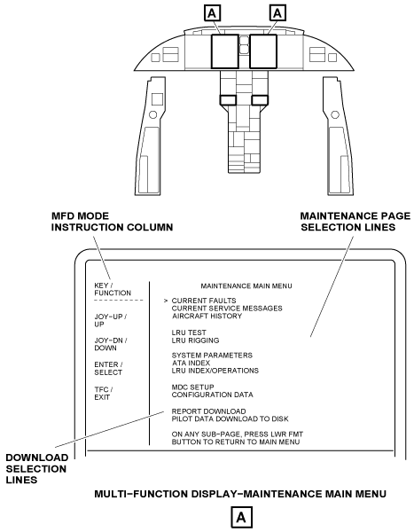
Maintenance Main Menu
When set to the maintenance diagnostic mode, the primary display on the MFD is the Maintenance Main Menu Page.
From the Maintenance Main Menu Page, the personnel can do one of the maintenance-page selections that follow:
- CURRENT FAULTS
- CURRENT SERVICE MESSAGES
- AIRCRAFT HISTORY
- LRU TEST
- LRU RIGGING
- SYSTEM PARAMETERS
- ATA INDEX
- LRU INDEX/OPERATIONS
- MDC SETUP
- CONFIGURATION DATA
Also, from the MAINTENANCE MAIN MENU page, the personnel can do the selection of one of the download functions that follow:
- REPORT DOWNLOAD
- PILOT DATA DOWNLOAD TO DISK
- LRU NVM DOWNLOAD
To do a selection from the Maintenance Main Menu, you put the cursor on the applicable line and push the CCP ENTER pushbutton.
The MFD mode instruction column on the Main Maintenance Menu page, tells the functions of the CCP controls as follows:
- The joystick UP is used to move the cursor up the page to the previous line.
- The joystick DOWN is used to move the cursor down the page to the line that follows.
- The ENTER pushbutton is used to show the display of the menu item that is adjacent to the cursor

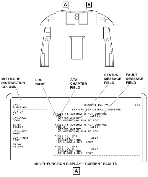
Current Faults
The CURRENT FAULTS page is a selection from the MAINTENANCE MAIN MENU.
The CURRENT FAULTS page supplies a list, in real time, of all LRUs which have a fail condition. The display adds or removes maintenance data, in real time, as fail conditions occur or are corrected. The indication NO FAULTS is shown if all LRUs are serviceable. The fail condition indications are shown between 0 and 60 sec after they are found. Thus, transient conditions are not shown.
The CURRENT FAULTS display is put into pages which show a maximum of four LRU data entries for each page. The CURRENT FAULTS are shown in a list with ATA chapter number and then in an alphabetical sequence with the LRU name. When there is more than one page, the joystick on the CCP lets the personnel move from one page to a different page. The joystick is pushed to the left (PREV) or right (NEXT). The page numbers are shown in the top right of the display. The display includes the data that follows:
- ATA Chapter
- LRU Name
- Status Message
- Fault Message
- MFD Mode Instruction Column.
The ATA chapter field shows the ATA chapter number and chapter name. The LRU name line shows the name and the identification number of the unit found defective. Each unit in the list is a possible defective LRU. But, it is necessary for the personnel to look at the STATUS field before corrective action. To do the selection of one of the LRUs on the list for display on the ADVANCED DIAGNOSTICS page, the cursor is put on the ATA chapter line, above the applicable LRU name. The STATUS message field shows one of the indications that follow:
- OFF/NO OUTPUT
- OVERHEAT
- FAILED
- MAINTENANCE
- DEFERRED MAINTENANCE
- LRU OK/INFO
The OFF/NO OUTPUT condition shows that no diagnostic words are received from that LRU. This shows a possible problem with a defective LRU or defective wiring.
The OVERHEAT condition shows that an LRU is in an overtemperature condition. The personnel can do a check of the fan/cooling system for that unit.
The FAILED condition shows that the diagnostic procedures found an LRU fail condition. The personnel can replace this LRU with a known good unit.
The FAILED/WIRING condition shows that the fault cause might be a failed LRU or a wiring problem.
The MAINTENANCE condition tells that maintenance is necessary on the LRU that is on the list.
The DEFERRED MAINT condition tells that the LRU is good, but usual maintenance (e.g. replacement of a battery) will be necessary in a short time.
The LRU OK/INFO condition tells that the LRU is good, and shows on the page to record an event (such as a yaw damper disengagement)
The FAULT MESSAGE field gives a description of the problem.
The MFD mode instruction column on the CURRENT FAULTS page, tells the functions of CCP controls as follows:
- The personnel can push the CCP joystick up (UP) to move the cursor up the page to the previous line
- The personnel can push the CCP joystick down (DOWN) to move the cursor down the page to the line that follows
- The personnel can push the CCP ENTER pushbutton (SELECT) to do a selection of the line adjacent to the cursor
- The personnel can push the CCP joystick left (PREV) to show the previous CURRENT FAULTS page
- The personnel can push the CCP joystick right (NEXT) to show the CURRENT FAULTS page that follows
- The personnel can push the CCP TR/WX pushbutton (RETURN) to go back to the MAINTENANCE MAIN MENU page
Adavanced Diagnostics
To show the ADVANCED DIAGNOSTICS page, the cursor on the CURRENT FAULTS page is put on the ATA chapter field line of the applicable LRU, and the CCP ENTER pushbutton is pushed.
Note:
Access to the ADVANCED DIAGNOSTICS page is also possible from the CURRENT SERVICE MESSAGES page and from the FAULT HISTORY page. Description of these two pages will follow.
The ADVANCED DIAGNOSTICS page shows the fault data for the applicable LRU.
The LRU field shows the name of the defective unit. The FAULT MESSAGE field gives a description of the problem. The ADVANCED DIAGNOSTICS page has the selection lines that follow:
- REFRESH
- HELP AND TROUBLESHOOTING TIPS
- SHOW MESSAGE DATA (or SHOW LRU DATA)
- SHOW IN HEXADECIMAL (or SHOW IN BINARY)
- Diagnostic word lines
The personnel can move the cursor to the applicable line and push the CCP ENTER pushbutton to do a selection. These selections update/give more data.
The selection of the REFRESH line causes the MDC to update the data on this page. LRU diagnostic words are updated and shown.
If the fault or service message is gone, the MDC shows MESSAGE NO LONGER ACTIVE. The message is shown on the dashed line at the bottom of the page.
The Selection Of The Help And Troubleshooting Tips line shows a page that has more data for that applicable fault or service message. This data is from a loadable file which contains a detailed fault description. If the data is available for a fault message, the MDC shows it on the HELP page related to that message.
The SHOW MESSAGE DATA (or SHOW LRU DATA) line is used to change between the two different displays that follow:
- LRU DIAGNOSTIC DATA display
- DATA USED TO DETERMINE MESSAGE display
The selection of the SHOW LRU DATA line shows the LRU DIAGNOSTIC DATA display. The LRU DIAGNOSTIC DATA fields show the diagnostic words for the LRU selection. A maximum of ten diagnostic words can show.
The selection of the SHOW MESSAGE DATA line shows the DATA USED TO DETERMINE MESSAGE display. This display shows the diagnostic words that caused the fault message to be recorded. The diagnostic words can be from other LRUs. This display shows all the diagnostic words that were used in the MDC diagnostic logic equation. The diagnostic words show the word label and then bits 31 to 9 from left to right.
The SHOW IN HEXADECIMAL (or SHOW IN BINARY) line is used to change between the two different format displays that follow:
- HEXADECIMAL Format Display
- BINARY Format Display
The selection of the SHOW IN HEXADECIMAL line shows the diagnostic words in hexadecimal format. The hexadecimal format shows the diagnostic word label, the LRU NAME, and the six-digit hexadecimal diagnostic word. The SHOW IN HEXADECIMAL format is used to show the LRU NAME related to the diagnostic words in the SHOW MESSAGE DATA format.
The selection of the SHOW IN BINARY line shows the diagnostic words in binary format. The binary format shows the diagnostic word label and bits 31 to 9 from left to right.
The bottom of the page shows the instructions USE TAB TO SWITCH BETWEEN DATA ITEMS AND OPERATION BUTTONS. The data items that show are diagnostic words. The operation buttons are the REFRESH, HELP AND TROUBLESHOOTING TIPS, SHOW LRU DATA, SHOW MESSAGE DATA, SHOW IN HEXADECIMAL, and SHOW IN BINARY selection lines (at the top of the page).
The personnel can use the CCP SKIP pushbutton (TAB) to move the cursor from the selection lines to the diagnostic words.
The selection of a diagnostic word label on the ADVANCED DIAGNOSTICS page causes the DATA READER page to show.
The DATA READER page contains more data about the diagnostic word label. The condition of each bit is shown on this page (1, 0, or a dash if no data is received). The DATA READER page contains the definition of the bits for the diagnostic word label.
The MFD mode instruction column on the ADVANCED DIAGNOSTICS page, tells the functions of CCP controls as follows:
- The personnel can push the CCP joystick up (UP) to move the cursor up the page to the previous line
- The personnel can push the CCP joystick down (DOWN) to move the cursor down the page to the line that follows
- The personnel can push the CCP ENTER pushbutton (SELECT) to do a selection of the line adjacent to the cursor
- The personnel can push the CCP joystick left (PREV) to show the previous ADVANCED DIAGNOSTICS page
- The personnel can push the CCP joystick right (NEXT) to show the next ADVANCED DIAGNOSTICS page
- The personnel can push the CCP SKIP pushbutton (TAB) to switch between data items and the operation buttons
- The personnel can push the CCP TR/WX (RETURN) to go back to the MAINTENANCE MAIN MENU page.
Data Reader
The selection of a diagnostic word label on the ADVANCED DIAGNOSTICS page causes the DATA READER page to show. The DATA READER page contains more data about the diagnostic word label. The top line of the Data READER page shows the diagnostic word label and the LRU name. The other lines show bit data for the related diagnostic word label. The page contains one line of data about each bit for the applicable label. The condition of each bit is shown on the page (1, 0, or a dash if there is no data received), together with bit definitions.
The MFD mode instruction column on the DATA READER page, tells the functions of the CCP controls as follows:
- The personnel can push the CCP joystick left (PREV) to show the previous DATA READER page
- The personnel can push the CCP joystick right (NEXT) to show the DATA READER page that follows
- The personnel can push the CCP TR/WX pushbutton (RETURN) to go back to the higher-level maintenance page


Current Service Message
The CURRENT SERVICE MESSAGES page is a selection from the MAINTENANCE MAIN MENU. The CURRENT SERVICE MESSAGES page shows a list of service messages that are sent to the DCU from the MDC. This is a dynamic display that updates as service messages occur or stop.
The list is put into pages that contain a maximum of four LRU data entries on a page. The CURRENT SERVICE MESSAGES page has the ATA/LRU/STATUS/SERVICE MESSAGE column and the MFD mode instruction column.
The ATA/LRU/STATUS/SERVICE MESSAGE column shows each unit and gives the related service message. Data fields show data in real time for each entry.
The ATA/LRU/STATUS/SERVICE MESSAGE column includes fields for LRU names, ATA chapter numbers and names, status messages, service messages, and component identifiers (ID). Maintenance is necessary for the unit that is shown in the LRU name field.
The status message field shows DEFERRED MAINT or MAINTENANCE messages.
The DEFERRED MAINT condition tells that the LRU is good, but usual maintenance (e.g. replacement of a battery) will soon be necessary.
The MAINTENANCE condition shows that maintenance is necessary for the LRU. The service message field gives a description of the problem.
The personnel can move the cursor to a specific LRU and push the CCP ENTER pushbutton for the selection of the ADVANCED DIAGNOSTICS page. On the ADVANCED DIAGNOSTICS page the selection of the VIEW DETAILED DIAGNOSTIC DATA line opens the DETAILED DIAGNOSTIC DATA page. The selection of the diagnostic word label on the DETAILED DIAGNOSTIC DATA page causes the DATA READER page to show. The DATA READER page will give the bit definitions of the diagnostic word.
The MFD mode instruction column on the CURRENT SERVICE MESSAGES page, tells the functions of the CCP controls as follows:
- The personnel can push the CCP joystick up (UP) to move the cursor up the page to the previous line
- The personnel can push the CCP joystick down (DOWN) to move the cursor down the page to the line that follows
- The personnel can push the CCP ENTER pushbutton (SELECT) to do a selection of the line adjacent to the cursor
- The personnel can push the CCP joystick left (PREV) to show the previous CURRENT SERVICE MESSAGES page
- The personnel can push the CCP joystick right (NEXT) to show the next CURRENT SERVICE MESSAGES page
- The personnel can push the CCP TR/WX pushbutton (RETURN) to go back to the MAINTENANCE MAIN MENU page

Aircraft History
The AIRCRAFT HISTORY page is a selection from the MAINTENANCE MAIN MENU. The AIRCRAFT HISTORY page shows a list of history files that the personnel can get. The AIRCRAFT HISTORY page shows the FAULT HISTORY line, SERVICE MESSAGE HISTORY line, FLIGHT LEG SUMMARY line, and the MFD mode instruction column. The personnel can move the cursor to the applicable history line and push the CCP ENTER pushbutton to do a selection of the adjacent related history page.
The MFD mode instruction column on the AIRCRAFT HISTORY page, tells the functions of the CCP controls as follows:
- The personnel can push the CCP joystick up (UP) to move the cursor up the page to the previous line
- The personnel can push the CCP joystick down (DOWN) to move the cursor down the page to the line that follows
- The personnel can push the CCP ENTER pushbutton (SELECT) to do a selection of the line adjacent to the cursor
- The personnel can push the CCP TR/WX pushbutton (RETURN) to go back to the MAINTENANCE MAIN MENU page
Fault History
The FAULT HISTORY page is a selection from the AIRCRAFT HISTORY page.
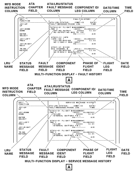
The FAULT HISTORY page is a report of the LRU fault entries that have shown before on the CURRENT FAULTS page. The LRU fault entries come into view when a fault condition has been found. The FAULT HISTORY is put into pages that contain a maximum of four LRU entries on a page. The last fault that was found shows at the top of page 1. Page numbers show in the upper right of the display. The FAULT HISTORY page has a data column and an MFD mode instruction column.
The data column of the FAULT HISTORY page shows the data that follow:
- ATA Chapter
- LRU Name
- Status
- Fault Message
- COMP-ID Leg
- Date/Time
- Phase-of-flight
The ATA chapter field gives the ATA chapter number of the unit. Faults are shown first in ATA chapter number sequence and then in LRU name sequence.
The LRU name field gives for each LRU fault entry, the name of the unit that was found defective during the flight or flight leg. Each unit shown is a possible LRU with a fail condition, but personnel must look at the STATUS field before corrective action.
The STATUS field shows FAILED, OFF/NO OUTPUT, OVERHEAT, LRU OK/INFO, DEFERRED MAINT, MAINTENANCE, or (blank) conditions. The FAILED condition shows a possible LRU fail-condition. The personnel can replace this LRU with a known good unit.
The OFF/NO OUTPUT condition shows that no diagnostic words are received from that LRU. This shows a possible problem with the power which is supplied to the LRU.
The OVERHEAT condition shows that an LRU is in an overtemperature condition. The personnel can examine the fan/cooling system for that unit.
The LRU OK/INFO condition shows that the LRU is good, and shows on the page to record an event (such as a yaw damper disengagement).
The DEFERRED MAINT condition tells that the LRU is good, but usual maintenance (e.g. replacement of a battery) will soon be necessary. The MAINTENANCE condition tells that maintenance is necessary for the LRU.
The FAULT MESSAGE field gives a description of the problem. The component identifier/flight leg (COMP-ID/LEG) column gives a list of the LRU component identifiers and the flight leg number during which the fault occurred.
The TIME/DATE column is a list of the time and date the fault occurred. The phase-of-flight line contains the intermittent count indication, the flight number, and the phase of flight (ground, air, or taxi).
The personnel can move the cursor to a specific LRU and push the CCP ENTER pushbutton to show the ADVANCED DIAGNOSTICS page for that LRU.
The MFD mode instruction column on the FAULT HISTORY page, tells the functions of the CCP controls as follows:
- The personnel can push the CCP joystick up (UP) to move the cursor up the page to the previous line
- The personnel can push the CCP joystick down (DOWN) to move the cursor down the page to the line that follows
- The personnel can push the CCP ENTER pushbutton (SELECT) to do a selection of the line adjacent to the cursor
- The personnel can push the CCP joystick left (PREV) to show the previous FAULT HISTORY page
- The personnel can push the CCP joystick right (NEXT) to show the FAULT HISTORY page that follows
- The personnel can push the CCP TR/WX pushbutton (RETURN) to go back to the higher-level maintenance page.
Service Message History
The SERVICE MESSAGE HISTORY page is a selection from the AIRCRAFT HISTORY page.
The SERVICE MESSAGE HISTORY page shows a list of service messages that the MDC found, or for which the DCU made a report. This list is in pages that contain a maximum of four LRU data entries. When there is more than one page, the personnel can push the CCP joystick left or right to do a selection between pages. Page numbers are shown in the upper right corner of the display.
The SERVICE MESSAGE HISTORY page has the data column and the MFD mode instruction column. The data column of the SERVICE HISTORY page shows the data that follows:
- ATA Chapter
- LRU Name
- Status
- Fault Message
- COMP-ID Leg
- Date/Time
- Phase-of-flight
The service messages are given as an ATA chapter number, and then in LRU name sequence. The ATA chapter field shows the ATA chapter number of the unit. The LRU field shows the name of the unit for which maintenance is necessary. The STATUS message field shows DEFERRED MAINT or MAINTENANCE messages. The DEFERRED MAINT condition shows the LRU is good, but maintenance is necessary.
The FAULT MESSAGE field gives a description of the problem. The COMP-ID/LEG column shows the LRU component identifier and the flight leg number during which the fault was shown. The TIME/DATE column lists the time and date the fault was shown. The phase-of-flight line contains the intermittent count indication, the flight number, and the phase of flight (ground, air, or taxi). The LRU name can be a selection to show the data ADVANCED DIAGNOSTICS page.
The personnel can move the cursor to the LRU and push the CCP ENTER pushbutton to do a selection of the ADVANCED DIAGNOSTICS page.
The MFD mode instruction column on the SERVICE MESSAGE HISTORY page, tells the functions of the CCP controls as follows:
- The personnel can push the CCP joystick down (DOWN) to move the cursor down the page adjacent to the line
- The personnel can push the CCP ENTER pushbutton (SELECT) to do the selection of the line adjacent to the cursor
- The personnel can push the CCP joystick left (PREV) to show the previous SERVICE MESSAGE HISTORY page
- The personnel can push the CCP joystick right (NEXT) to show the next SERVICE MESSAGE HISTORY page
- The personnel can push the CCP TR/WX pushbutton (RETURN) to go back to the higher-level maintenance page
Flight Leg Summary
The FLIGHT LEG SUMMARY page is a selection from the AIRCRAFT HISTORY page. The FLIGHT LEG SUMMARY is put together into pages that contain a maximum of 17 entries. The FLIGHT LEG SUMMARY page gives the personnel a procedure to find maintenance related events that were recorded on the applicable flight leg. The most recent flight leg is shown at the top of page 1. The page numbers are shown in the upper right of the display. The FLIGHT LEG SUMMARY page contains the LEG# column, a FAULT column and a SERVC MSG column. The LEG# column shows each flight leg number. The FAULT column shows the number of faults found for that flight leg. The SERVC MSG column shows the number of service messages recorded for that flight leg.
The data loader is used to download the FLIGHT LEG SUMMARY reports to diskette/USB memory drive (refer to the REPORT DOWNLOAD function line on the MAINTENANCE MENU page).
The MFD mode instruction column on the FLIGHT LEG SUMMARY page, tells the functions of the CCP controls as follows:
- The personnel can push the CCP joystick up (UP) to move the cursor up the page to the previous line
- The personnel can push the CCP joystick down (DOWN) to move the cursor down the page adjacent to the line
- The personnel can push the CCP ENTER pushbutton (SELECT) to do the selection of the line adjacent to the cursor
- The personnel can push the CCP joystick left (PREV) to show the previous page
- The personnel can push the CCP joystick right (NEXT) to show the page that follows
- The personnel can push the CCP TR/WX pushbutton (RETURN) to go back to the higher-level maintenance page
Flight Leg Detail
The FLIGHT LEG DETAIL page is a selection from the FLIGHT LEG SUMMARY page. The FLIGHT LEG DETAIL page shows all the fault messages and service messages for that flight leg. This page consists of the data that follow:
- ATA Chapter
- LRU Name
- Flight LEG
- Fault/Service Message
- Component Identifier
- Date/Time
- Phase-of-flight
- MFD Mode Instruction Column
The ATA chapter field gives the ATA chapter number of the unit. The LRU name field gives the name of the unit that was found defective. The flight LEG field gives the number of the flight leg for which maintenance data is shown.
The FAULT/SERVICE message fields give a description of the problem. The component identifier gives reference of the unit that shows a fault.
The date/time data gives the date and time at which the fault occurred. The phase-of-flight field gives the phase (ground, air, or taxi) during which the fault occurred.
The MFD mode instruction column on the FLIGHT LEG DETAIL page, tells the functions of the CCP controls as follows:
- The personnel can push the CCP joystick up (UP) to move the cursor up the page to the previous line
- The personnel can push the CCP joystick down (DOWN) to move the cursor down the page adjacent to the line
- The personnel can push the CCP ENTER pushbutton (SELECT) to do the selection of the line adjacent to the cursor
- The personnel can push the CCP joystick left (PREV) to show the previous page
- The personnel can push the CCP joystick right (NEXT) to show the next page
- The personnel can push the CCP TR/WX pushbutton (RETURN) to go back to the higher-level maintenance page


LRU Test
The selection of the LRU TEST line on the MAINTENANCE MAIN MENU causes the LRU INDEX page to show, with the FILTER selection set to TESTABLE LRUS.
The LRU INDEX page has the FILTER field, cursor ">", LRU name field, instruction field, and the MFD mode instruction column. While the FILTER field shows TESTABLE LRUS, the MDC can start an LRU test (one LRU at a time). When the target LRU test selection is set for test on the display, the MDC sends a test version ID request to the LRU.
The MDC compares the test version ID received from the LRU to the ID in the LRUs test files.
If the ID data is the same, the MDC sends a command to the specified LRU to start the test. The LRU tells the MDC which display to show. The display for each of the tests is kept in the MDC. Display data can be loaded as tables into the MDC.
The data on the display includes instructions, warnings, or rigging pre-conditions. The tests are interactive with instructions on the display to the operator to perform actions with the test. The MDC will send the abort command if the test is stopped. The LRU stops the test if there is a command from the MDC or if a dangerous condition occurs. At the end of the test, the MDC shows the test pass/fail data from the LRU.
The FILTER field shows the personnel how the LRU list was filtered. Possible filter selections are TESTABLE LRUS, RIGGABLE LRUS, REPORTING LRUS, LRUS BY ATA, and ALL LRUS ALPHABETICAL.
The instruction field at the bottom of the display shows USE THE TAB TO SWITCH BETWEEN LRU LIST AND FILTER BUTTON.
The personnel can push the CCP SKIP pushbutton (TAB) to move the cursor between the FILTER field and the LRU list.
When the FILTER field is set, the personnel can push the CCP ENTER pushbutton to change the filter selection.
The LRU name field shows the filtered TESTABLE LRU list. The LRUs that do not give a report for a system are listed below the last LRU that does give a report for that system.
The personnel can push the CCP joystick up or down to move the cursor to the LRU. The personnel can push the CCP ENTER pushbutton to do the selection of the LRU.
The personnel can also push the CCP ENTER pushbutton to get a view of the LRU test procedure page for that LRU.
The MFD mode instruction column on the LRU TEST page, tells the functions of the CCP controls as follows:
- The personnel can push the CCP joystick up (UP) to move the cursor up the page to the previous line
- The personnel can push the CCP joystick down (DOWN) to move the cursor down the page adjacent to the line
- The personnel can push the CCP ENTER pushbutton (SELECT) to do the selection of the line adjacent to the cursor
- The personnel can push the CCP joystick left (PREV) to show the previous page
- The personnel can push the CCP joystick right (NEXT) to show the next page
- The personnel can push the CCP SKIP pushbutton (TAB) to do the selection of the LRU list and the filter button
- The personnel can push the CCP TR/WX pushbutton (RETURN) to go back to the higher-level maintenance page

LRU Rigging
The selection of the LRU RIGGING line on the MAINTENANCE MAIN MENU causes the LRU INDEX page to show, with the FILTER selection set to RIGGABLE LRUS.
The LRU INDEX page shows the FILTER field, cursor ">", LRU name field, instruction field, and the MFD mode instruction column. While the FILTER field shows RIGGABLE LRUS, the MDC can start an LRU rigging procedure.
When the target LRU is a selection for rigging on the display, the MDC sends a rigging version ID request to the LRU. The MDC compares the rigging version ID received from the LRU to the ID kept in the LRUs rigging files.
If the IDs are the same, the MDC sends out a command to the set LRU to start the procedure.
The LRU sends a code to the MDC to show the correct display. The MDC shows the correct display. The displays for each of the procedures are kept in the MDC. The rigging display data can be loaded as tables into the MDC. The data on the display includes instructions, warnings, or test prerequisites.
The rigging procedure is interactive and instructions are given on the display. The personnel can do a selection of the correct procedures. The MDC will send the abort command if the test is stopped. The LRU stops the test if there is a command from the MDC or if a dangerous condition occurs. At the end of the test, the MDC shows the test pass/fail data from the LRU.
The FILTER field shows the personnel how the LRU list was filtered. Possible filter selections are TESTABLE LRUS, RIGGABLE LRUS, REPORTING LRUS, LRUS BY ATA, and ALL LRUS ALPHABETICAL.
The instruction field at the bottom of the display shows USE THE TAB TO SWITCH BETWEEN LRU LIST AND FILTER BUTTON. The personnel can push the CCP SKIP pushbutton (TAB) to move the cursor between the FILTER field and the LRU list. When the FILTER field is set, the personnel can push the CCP ENTER pushbutton to change the filter selection.
The personnel can push the CCP joystick up or down to move the cursor to the LRU. The personnel can push the CCP ENTER pushbutton to do the selection of the LRU.
The personnel can also push the CCP ENTER pushbutton to get a view of the LRU test procedure page for that LRU.
The MFD mode instruction column on the LRU RIGGING page, tells the functions of the CCP controls as follows:
- The personnel can push the CCP joystick up (UP) to move the cursor up the page to the previous line
- The personnel can push the CCP joystick down (DOWN) to move the cursor down the page adjacent to the line
- The personnel can push the CCP ENTER pushbutton (SELECT) to do the selection of the line adjacent to the cursor
- The personnel can push the CCP joystick left (PREV) to show the previous page
- The personnel can push the CCP joystick right (NEXT) to show the page that follows
- The personnel can push the CCP SKIP pushbutton (TAB) to do a selection of the LRU list and the filter button
- The personnel can push the CCP TR/WX pushbutton (RETURN) to go back to the higher-level maintenance page

System Parameters
The SYSTEM PARAMETERS page is a selection from the MAINTENANCE MAIN MENU. The SYSTEM PARAMETERS page has the cursor ">", a PARAMETERS column, a VALUE column, and the MFD mode instruction column.
The monitored parameters are put into the maintenance tables. The PARAMETER column shows the parameters that are monitored.
The VALUE column shows the parameter values and units of measure.
A parameter selection on the SYSTEM PARAMETERS page causes the DATA READER page to show. The DATA READER page contains more data about the parameter word label. The condition of each bit is shown on this page (1, 0, or a dash if no data received). The DATA READER page shows the bits for the applicable label.
The MFD mode instruction column on the SYSTEM PARAMETERS page, tells the functions of the CCP controls as follows:
- The personnel can push the CCP joystick up (UP) to move the cursor up the page to the previous line
- The personnel can push the CCP joystick down (DOWN) to move the cursor down the page adjacent to the line that follows
- The personnel can push the CCP ENTER pushbutton (SELECT) to do the selection of the line adjacent to the cursor
- The personnel can push the CCP joystick left (PREV) to show the previous page
- The personnel can push the CCP joystick right (NEXT) to show the page that follows
- The personnel can push the CCP TR/WX pushbutton (RETURN) to go back to the higher-level maintenance page

ATA Index
The ATA INDEX page is a selection from the MAINTENANCE MAIN MENU. The ATA INDEX page shows a list of the ATA chapters for the LRUs on the aircraft. The ATA INDEX page has the FILTER field, cursor ">", ATA chapter and name field, instruction field, and the MFD mode instruction column. Page numbers show in the top right of the display.
The FILTER field shows the personnel how to filter the ATA chapters. Possible filter selections are ALL CHAPTERS, TESTABLE CHAPTERS, and RIGGABLE CHAPTERS. When the FILTER field is set, push the CCP ENTER pushbutton to change the filter selection.
The ATA chapter/name field shows the filtered ATA chapter list. The personnel can move the cursor to a given ATA chapter for selection. The personnel can push the CCP ENTER pushbutton to get a view of the LRUs that are in that chapter. The LRUs are shown on the LRU INDEX page (access to the LRU INDEX page is also possible from the MAINTENANCE MAIN MENU page).
The MFD mode instruction column on the ATA INDEX page, tells the functions of the CCP controls as follows:
- The personnel can push the CCP joystick down (DOWN) to move the cursor down the page adjacent to the line
- The personnel can push the CCP ENTER pushbutton (SELECT) to do the selection of the line adjacent to the cursor
- The personnel can push the CCP joystick left (PREV) to show the previous page
- The personnel can push the CCP joystick right (NEXT) to show the page that follows
- The personnel can push the CCP SKIP pushbutton (TAB) to do the selection of the LRU list and the filter button
- The personnel can push the CCP TR/WX pushbutton (RETURN) to go back to the MAINTENANCE MAIN MENU page

LRU Index/Operations
LRU Index
The LRU INDEX/OPERATIONS is a selection from the MAINTENANCE MAIN MENU that causes the LRU INDEX page to show. The LRU INDEX page shows a list of the LRUs on the aircraft. This page has the FILTER field, cursor ">", LRU name field, instruction field, and the MFD mode instruction column. The FILTER field shows the personnel how the LRU list was filtered. The possible filter selections are REPORTING LRUS, LRUS BY ATA, ALL LRUS ALPHABETICAL, TESTABLE LRUS, and RIGGABLE LRUS. The personnel can push the CCP SKIP pushbutton to do a selection between the filter button and the LRU list.
The LRU name field shows the filtered LRU list. The LRUs that do not show data for a system are listed below the last LRU that shows data for that system. The personnel can move the CCP joystick to do the selection of an LRU. The personnel can push the CCP ENTER pushbutton to set the LRU and get a view of the LRU OPERATIONS page.
The MFD mode instruction column on the LRU INDEX page, tells the functions of the CCP controls as follows:
- The personnel can push the CCP joystick up (UP) to move the cursor up the page to the previous line
- The personnel can push the CCP joystick down (DOWN) to move the cursor down the page adjacent to the line that follows
- The personnel can push the CCP ENTER pushbutton (SELECT) to do the selection of the line adjacent to the cursor
- The personnel can push the CCP joystick left (PREV) to show the previous page
- The personnel can push the CCP joystick right (NEXT) to show the page that follows
- The personnel can push the CCP SKIP pushbutton (TAB) to do the selection of the LRU list and the filter button
- The personnel can push the CCP TR/WX pushbutton (RETURN) to go back to the higher-level maintenance page
LRU Operations
The LRU OPERATIONS page shows when an LRU is a selection from the LRU INDEX page.
The LRU OPERATIONS page gives access to the LRU test and rigging procedures and the LRU DIAGNOSTIC DATA.
The LRU OPERATIONS page has the LRU name field, current status field, cursor ">", and the TEST line.
The LRU OPERATIONS page has also the RIGGING line, SHOW IN HEXADECIMAL line, LRU DIAGNOSTIC DATA field, instruction field, and the MFD mode instruction column.
The LRU name field shows the LRU selection. The CURRENT STATUS field shows the LRU condition from the diagnostic word. The FAULTS PRESENT shows if the diagnostic word SSM (sign status matrix) is a fail condition warning.
The TEST line is used to do the selection of the SELECT TEST page. The RIGGING line is used to do the selection of the SELECT PROCEDURE page.
The personnel can move the CCP joystick to do the selection of the TEST or RIGGING line. The personnel can push the CCP ENTER pushbutton to show the TEST or RIGGING page.
The LRU DIAGNOSTIC DATA fields show the diagnostic words for the LRU selection. A maximum of ten diagnostic words can show. The diagnostic word bits are not shown (dash lines) if the word is not received.
The SHOW IN HEXADECIMAL (or the SHOW IN BINARY) line is used to do the selection of the diagnostic words shown in a hexadecimal or binary format. The selection of the SHOW IN HEXADECIMAL line shows the hexadecimal format. The hexadecimal format shows the diagnostic word label, the LRU NAME, and the six-digit hexadecimal diagnostic word.
The selection of the SHOW IN BINARY line shows the word label and bits 9 to 31 from right to left.
The bottom of the page shows the instructions USE TAB TO SWITCH BETWEEN DATA ITEMS AND OPERATION BUTTONS. The data items are the diagnostic words that are shown. The operation buttons are the TEST, RIGGING, SHOW IN HEXADECIMAL, and SHOW IN BINARY selection lines at the top of the page. The personnel can use the CCP SKIP pushbutton (TAB) to do the selection of the diagnostic words.
The selection of the diagnostic word label on the LRU OPERATIONS page causes the DATA READER page to show. The DATA READER page shows the data about the diagnostic word label. The condition of each bit is shown on the DATA READER page (1, 0, or a dash if no data is received).
The MFD mode instruction column on the LRU OPERATION page, tells the functions of the CCP controls as follows:
- The personnel can push the CCP joystick up (UP) to move the cursor up the page to the previous line
- The personnel can push the CCP joystick down (DOWN) to move the cursor down the page adjacent to the line that follows
- The personnel can push the CCP ENTER pushbutton (SELECT) to do the selection of the line adjacent to the cursor
- The personnel can push the CCP joystick left (PREV) to show the previous page
- The personnel can push the CCP joystick right (NEXT) to show the page that follows
- The personnel can push the CCP TR/WX pushbutton (RETURN) to go back to the higher-level maintenance page

MDC Setup
The MDC SETUP page is a selection from the MAINTENANCE MAIN MENU. The MDC SETUP page has the selection lines that follow:
- SET AIRCRAFT IDENTIFICATION
- SET AIRCRAFT CLOCK
- LOAD FILES FROM DISK
- FILE BROWSER
Note:
There are some functions which do not show on the MDC SETUP page during usual operation. These functions are hidden to prevent unwanted changes to the MDC data. The personnel can show and activate the hidden functions with the use of a password.
With the SET AIRCRAFT IDENTIFICATION line, the flight or maintenance crew can set the aircraft identification number (AIN). The AIN is used for identification of data files and is transmitted to aircraft LRUs.
With the SET AIRCRAFT CLOCK line, the flight or maintenance crew can set the time and date on the aircraft clock.
The selection of the FILE BROWSER line shows a list of test and rigging file names that includes dates and file sizes.
The LOAD FILES FROM DISK line lets the flight or maintenance crew upload table files from the data loader. The table files include test pages, rigging pages, and fault equation data.
The MFD mode instruction column on the MDC SET UP page, tells the functions of the CCP controls as follows:
- The personnel can push the CCP joystick up (UP) to move the cursor up the page to the previous line
- The personnel can push the CCP joystick down (DOWN) to move the cursor down the page adjacent to the line that follows
- The personnel can push the CCP ENTER pushbutton (SELECT) to do the selection of the line adjacent to the cursor
- The personnel can push the CCP TR/WX pushbutton (RETURN) to go back to the MAINTENANCE MAIN MENU page
Set Aircraft Identification
The SET AIRCRAFT IDENTIFICATION page is a selection from the MDC SET UP page.
The flight or maintenance crew use the SET AIRCRAFT IDENTIFICATION page to set the aircraft identification. The MDC stores the aircraft identification in the NVM. The aircraft identification and error messages or warning messages show on the display. The SET AIRCRAFT IDENTIFICATION page has the IDENT line, the alphanumeric selection grid, and the MFD mode instruction column.
The NEW AIRCRAFT IDENT value is set to the CURRENT AIRCRAFT IDENT. If no value was given before, then the fields show no value. An up-arrow cursor is put in the position that is below the first character in the NEW AIRCRAFT IDENT field.
If a default character or space (from CURRENT AIRCRAFT IDENT field) is shown, then the character is highlighted in amber in the NEW AIRCRAFT IDENT field and the alphanumeric selection grid.
The personnel can use the CCP joystick to move the cursor UP, DOWN, LEFT, and RIGHT on the alphanumeric selection grid.
The number, letter, or space can be a selection if highlighted in amber. When the first character in the NEW AIRCRAFT IDENT is correct, the personnel push the CCP ENTER pushbutton to do the selection of the character. Personnel can also push the CCP ENTER pushbutton to move the cursor again into a position below the characters that follow. If a character is not to change, the personnel can push the ENTER (select) pushbutton to do the selection of the default character.
Dash characters are not accepted as valid characters. The personnel can use the space (SPC) character in place of a dash. Selection of the <– symbol located to the left of SPC will insert a space to the left side. Selection of the –> symbol located to the right of SPC will insert a space to the right side.
When the NEW AIRCRAFT IDENT field is completed, personnel can push the CCP TR/WX pushbutton (ACCEPT) to accept the data. The CURRENT AIRCRAFT IDENT value is set to the NEW AIRCRAFT IDENT and the display shows the MDC SETUP page.
To cancel, personnel can push the CCP TFC pushbutton (CANCEL). The NEW AIRCRAFT IDENT value is set to the CURRENT AIRCRAFT IDENT and the display shows the MDC SETUP page.
The MDC SETUP page also has HIDDEN FUNCTIONS that can be accessed with the use of the CCP.
Note:
These functions are hidden to prevent inadvertent alteration or deletion of MDC data. These functions are activate only by the pass code sequence as listed below. These functions will continue to show on the MDC SETUP page until MAINTENANCE mode is exited, or airplane cold start occurs, or power up is initiated.
To access the MDC SETUP HIDDEN FUNCTIONS the user must enter the following pass code sequence with the use of the CCP joystick and ENTER button:
- LEFT, RIGHT, UP, ENTER, DOWN
Completing the pass code sequence will show four additional items on the MDC SETUP page:
- RESET FAULT HISTORY
- RESET SERVICE MESSAGE HISTORY
- RESET ALL DATA FILES
- DELETE ALL CHECKLIST FILES
Selection of the RESET FAULT HISTORY line will delete the faults generated and stored by the airplane systems.
Selection of the RESET SERVICE MESSAGE HISTORY line will delete the service messages generated and stored by the airplane systems.
Selection of the RESET ALL DATA FILES line will delete the MDC history information. This will reset the engine trend data, engine exceedances, LRU fault history, and maintenance message files.
Note:
Due to warrant considerations, it is recommended that the MDC data be downloaded to a USB before performing the RESET ALL DATA FILES operation.
Selection of the DELETE ALL CHECKLIST FILES line will delete all previously loaded checklists.
The MFD mode instruction column on the SET AIRCRAFT IDENTIFICATION page, tells the functions of the CCP controls as follows:
- The personnel can push the CCP joystick up (UP) to move the cursor up on the alphanumeric grid
- The personnel can push the CCP joystick down (DOWN) to move the cursor down on the alphanumeric grid
- The personnel can push the CCP ENTER pushbutton (SELECT) to do the selection of a character on the alphanumeric grid
- The personnel can push the CCP joystick left (PREV) to move the cursor to the left on the alphanumeric grid
- The personnel can push the CCP joystick right (RIGHT) to move the cursor to the right
- The personnel can push the CCP TR/WX pushbutton (ACCEPT) to accept the NEW AIRCRAFT IDENT
- The personnel can push the CCP TFC pushbutton (CANCEL) to cancel the NEW AIRCRAFT IDENT
Set Aircraft Clock
The SET AIRCRAFT CLOCK page is a selection from the MDC SET UP page. The flight or maintenance crew can set the MDC clock on the SET AIRCRAFT CLOCK page. The clock set operation is available only when the DCU does not receive the global positioning system (GPS) or ARINC (ships) clock. The SET AIRCRAFT CLOCK page has a top line that shows CURRENT TIME and CURRENT DATE data. Other lines show the selections that follow:
- SET NEW TIME
- SET NEW DATE
- ACCEPT
- CANCEL
The SET NEW TIME line let the personnel set a new time value, in the format hh:mm. If the cursor is adjacent to the SET NEW TIME line, the personnel push the CCP ENTER pushbutton to do the selection. The up-arrow cursor shows below the first character in the SET NEW TIME field. The personnel can use the CCP controls to move UP or DOWN through the numbers. The number above the cursor, can be a selection if highlighted in amber. When the first character of the SET NEW TIME field is correct, the personnel can push the CCP ENTER pushbutton. This makes a selection of the character.
The personnel can also push the CCP ENTER pushbutton to move the cursor again into a position below the character that follows. The process can be a selection for each character in the SET NEW TIME field. If it is not necessary to change a character, the personnel can push the ENTER (SELECT) pushbutton to do a selection of the default character.
When the selection of the last character in SET NEW TIME is done, the personnel can push the CCP ENTER pushbutton to do the selection of OK which sets the new current time value. When the SET NEW TIME procedure is completed, the cursor is put on the SET NEW DATE line. This causes data fields to show on the line with a dd-mm-yyyy format. These SET NEW DATE fields let the personnel set a new date value. The up-arrow cursor is put in position below the first character in the SET NEW DATE field. The personnel can use the CCP controls to do the selection UP or DOWN through the numbers and letters.
The character above the cursor, can be a selection if highlighted in amber. The personnel can push the CCP ENTER pushbutton to do a selection of the character. The up-arrow cursor moves below the character that follows. Personnel can do this when the first character of the SET NEW DATE field is correct. The process can be a selection for each character in SET NEW DATE field. If it is not necessary to change a character, the personnel can push the ENTER (select) pushbutton to do the selection of the default character.
When the CCP ENTER (SELECT) pushbutton is pushed for the last character in SET NEW DATE, the personnel can push the CCP ENTER pushbutton to do the selection of OK which sets the new current-date value.
When the SET NEW TIME and SET NEW DATE procedures are completed, the cursor moves to the ACCEPT line. The CCP ENTER pushbutton is pushed to ACCEPT (SELECT) the new time and date values. The MDC SET UP page shows with the new data.
If the cursor is put on the CANCEL line, and the CCP ENTER (SELECT) pushbutton is pushed, the changes are cancelled and the MDC SET UP page shows with no changes.
The MFD mode instruction column on the SET AIRCRAFT CLOCK page, tells the functions of the CCP controls to do the selection of one of the items (time or date) to set, and to enter the new values.
For the selection of the SET NEW TIME or SET NEW DATE line, the personnel can:
- Push the CCP joystick up (UP), to move the cursor up the page to the previous line
- Push the CCP joystick down (DOWN), to move the cursor down the page adjacent to the line that follows
- Push the CCP ENTER pushbutton (SELECT), to do the selection of the line adjacent to the cursor
To set new time and date values, the personnel can:
- Push the CCP joystick up (UP), to increase the number or value in the field above the up-arrow cursor
- Push the CCP joystick down (DOWN), to decrease the number or value in the character above the up-arrow cursor
- Push the CCP ENTER (SELECT) pushbutton, to do the selection of the number or value of the character above the up-arrow cursor
- Push the CCP ENTER pushbutton, with the cursor set adjacent to ACCEPT line, to accept the time and date changes
- Push the CCP ENTER pushbutton, with the cursor set adjacent to CANCEL line, to cancel the time and date changes
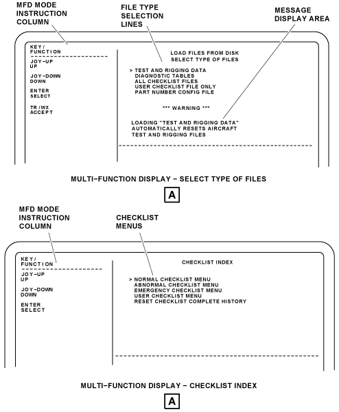
Load Files From Disk
The LOAD FILES FROM DISK page is a selection from the MDC SET UP page. The LOAD FILES FROM DISK page is used to do the selection of the type of files to install from the data loader. The new files from the disk are used for the functions that follow:
- To replace/update the files of an MDC
- To install files in an MDC that does not have files
- To install files in an MDC that had an unsuccessful installation and does not have files
- To install files in an MDC that has bad files
The data loader disk drive does file operations on a USB removable media. Database files must be stored in the root directory on the USB removable media device. Only one database file type can be stored in the directory at a time. Failure to use the root directory will cause an ERROR or FILES NOT FOUND message. The USB removable media device must be compatible with Mircorsoft FAT16 or FAT32 file systems, and must not contain any installed Windows-based programs. The minimum recommended USB removable media device storage size is 1 gigabyte (GB).
The data loader can read directories, read, write, or rename files, and delete files stored on the USB. The MDC diagnostic fault logic is operated from a set of tables that are in storage in the disk loadable files. The files have the data that gives the received ARINC words. The files have the logic to be operated by the data in the received ARINC words, and the maintenance tables. The DIAGNOSTIC TALBES operation installs new maintenance tables and the MDC automatically erases all flight leg history in storage in the NVRAM.
Note:
During a load operation, if more than one USB removable media device is installed in the data loader, the top USB port is the default port.
The LOAD FILES FROM DISK page has the selection lines that follow:
- Test And Rigging Data
- Diagnostic Tables
- All Checklist Files
- User Checklist File only
- Part Number Config File
Selection of one of these loading operations show a warning message that tells the operator that the MDC will automatically reset the applicable MDC history data.
The TEST AND RIGGING DATA selection causes a LOADING TEST AND RIGGING DATA display to show. The LOADING TEST AND RIGGING DATA function installs new test and rigging files and the MDC automatically erases the previous tests and rigging files in the NVM. The personnel install the new test and rigging files that are approved by Bombardier.
Selection of one of the DIAGNOSTIC TABLES lines will show a warning message that tells the operator that loading diagnostic data files will automatically reset the aircraft history data.
Note:
The LOADING DIAGNOSTIC TABLES function is not used in the field. The related data given in this section is for reference only.
The LOADING DIAGNOSTIC TABLES function installs new maintenance tables and the MDC automatically erases all flight leg history in storage in the NVM. The ALL CHECKLIST FILES or the USER CHECKLIST FILE ONLY selection causes an applicable LOADING CHECKLIST FILES or LOADING USER CHECKLIST FILE ONLY page to show. The ALL CHECKLIST FILES and USER CHECKLIST FILE ONLY functions install electronic checklists. The MDC can keep and show normal, abnormal, emergency, and user checklists.
The PART NUMBER CONFIG FILE selection line will show a warning message that tells the operator that loading a part number config file will automatically resets the aircraft part number config file.
The CKLST pushbutton on the CCP, when pushed, causes a CHECKLIST INDEX page to shown on the copilot MFD. This page contains four selection lines related to the type of checklists available. Selection and control of the CHECKLIST functions are done through the CCP joystick, and the CCP SKIP and ENTER pushbuttons.
The MFD mode instruction column on the LOAD FILES FROM DISK page, tells the functions of the CCP controls as follows:
- The personnel can push the CCP joystick up (UP) to move the cursor up the page to the previous line
- The personnel can push the CCP joystick down (DOWN) to move the cursor down the page adjacent to the line that follows
- The personnel can push the CCP ENTER pushbutton (SELECT) to do the selection of the line adjacent to the cursor
- The personnel can push the CCP TR/WX pushbutton (RETURN) to go back to the higher-level maintenance page (MDC SET UP page)
The selection of one of the LOAD FILES FROM DISK lines, causes an applicable loading file page to show. The loading file page shows the type of loading files (diagnostic data, test and rigging, or checklist files), the file name that is currently loading, a progress bar, and applicable messages related to the loading operation progress.
If the installation process is stopped before the successful installation of the new control file, the appropriate error message is shown. The personnel are told to PRESS MENU TO RETURN TO THE MAINTENANCE MENU. The MDC stays the same if the installation process is stopped before the installation of the new control file.
If the installation process is stopped after the control file is installed, the MDC has erased all the history files. The files in storage installed before are also erased. The MDC does not have valid files installed. The applicable error message is shown. The personnel are told to do a selection to CONTINUE and go back to the LOAD FILES FROM DISK page.
The list that follows shows a short explanation of MDC error messages that can be shown during the data loader operation:
- DBU UNAVAILABLE shows that another LRU uses the data loader at this time. When the data loader becomes available, the MDC files can be installed
- DBU FAULT 8A shows that the data loader has intermittent transmit fail-conditions
- DBU NOT RESPONDING shows that the DBU to MDC communications link is bad or the DBU is bad
- NO DISK/DBU FAULT shows that the DBU does not show a USB memory drive
- DISK UNFORMATTED shows that the USB memory drive is not correctly formatted
- DISK INVALID - MULT CTL FILES shows that the DBU found more than one file that has file extension = CTL
- INVALID CTL FILE shows that the strapping data contained in the uploaded control file does not agree with the configuration strapping unit (CSU) for the aircraft code. Possibly, something is wrong with the control file
- DISK INVALID - MISSING FILES shows that the files in lines 5 to 15 in the control file are not on the USB memory drive
- DISK TEMP BELOW 0 DEGREE shows that the temperature of the disk drive is less than the permitted minimum temperature
- PROTOCOL VIOLATION shows that the DBU saw an error in the MDC to DBU communications protocol
- READ/WRITE FAILURE shows that the DBU had a fail condition when it tried a write to diskette/USB memory drive
- RECEIVED DATA ERROR DETECTED shows that the DBU found an error in data received from MDC
- DBU FAULT 8E shows that the DBU has shown a floppy disk controller fault
- DBU FAULT 8F shows that the DBU has shown a track seek fail-condition
On the applicable loading-operation page, the personnel can do a CANCEL selection to stop the file loading operation before it is completed.
When the operation is completed successfully, the CANCEL selection becomes CONTINUE selection.
The personnel can:
- Push the CCP TR/WX pushbutton to return to the higher-level maintenance page
- Push the CCP LWR FRMT pushbutton to return to the MAINTENANCE MAIN MENU


Configuration Data
The CONFIGURATION DATA page is a selection from the MAINTENANCE MAIN MENU. The CONFIGURATION DATA page has the selections that follow:
- CSU DATA (LEFT)
- CSU DATA (RIGHT)
- MDC VERSION INFORMATION
- LRU CONFIGURATION DATA
- LRU SW PART NUMBER DATA
The CSU DATA (LEFT/RIGHT) selection gives access to the LEFT or RIGHT CONFIGURATION STRAPPING DATA page.
The MDC VERSION INFORMATION selection gives access to the MDC VERSION INFORMATION page.
The LRU CONFIGURATION DATA gives access to the LRU CONFIGURATION DATA page.
The LRU SW PART NUMBER DATA gives access to the SOFTWARE PART NUMBERS page.
The MFD mode instruction column on the CONFIGURATION DATA page, tells the functions of the CCP controls as follows:
- The personnel can push the CCP joystick up (UP) to move the cursor up the page to the previous line
- The personnel can push the CCP joystick down (DOWN) to move the cursor down the page adjacent to the line that follows
- The personnel can push the CCP ENTER pushbutton (SELECT) to do the selection of the line adjacent to the cursor
- The personnel can push the CCP TR/WX pushbutton (RETURN) to go back to the higher-level maintenance page (MAINTENANCE MAIN MENU page)
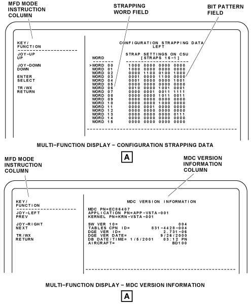
Configuration Strapping Data
The selection of the CSU DATA (LEFT) line on the CONFIGURATION DATA page, causes the display to show the CONFIGURATION STRAPPING DATA page for the left configuration strapping unit. LEFT or RIGHT shows below the page title to identify the left or right configuration strapping unit.
The CONFIGURATION STRAPPING DATA page contains the WORD column, the STRAP SETTINGS ON CSU (STRAPS 16-1) column, and the MFD mode instruction column.
The WORD column shows the strapping words from WORD 00 to WORD 15. The STRAP SETTINGS ON CSU column shows the bit pattern (16-1) related to the octal label 360 bits 24 to 9. The MDC shows the bit configuration of the left and right configuration strapping units. The left and right side CSUs are strapped the same.
The display shows the flight or maintenance crew if there are differences between the two strapping units. If a difference is shown, the strapping word that has the fault is highlighted in yellow.
The selection of a strapping word on the CONFIGURATION STRAPPING DATA page causes the DATA READER page to show.
The DATA READER page contains more data about the configuration strapping word. Each bit is shown on this page (1, 0, or a dash if no data is received). The DATA READER page has the definition of the bits for the label selection.
The MFD mode instruction column on the CONFIGURATION STRAPPING DATA LEFT/RIGHT page, tells the functions of the CCP controls as follows:
- The personnel can push the CCP joystick up (UP) to move the cursor up the page to the previous line
- The personnel can push the CCP joystick down (DOWN) to move the cursor down the page adjacent to the line that follows
- The personnel can push the CCP ENTER pushbutton (SELECT) to do the selection of the line adjacent to the cursor
- The personnel can push the CCP TR/WX pushbutton (RETURN) to go back to the higher-level maintenance page (CONFIGURATION DATA page)
MDC Version Information
The selection of the MDC VERSION INFORMATION line on the CONFIGURATION DATA page shows the MDC VERSION INFORMATION page. This page shows the version data that follow about the MDC:
- Boot Software Part Number
- Application Part Number
- KERNEL PN (kernel part number)
- RMA Version ID
- Software Version ID
- TABLES CPN ID (Table Collins part number (CPN) and identifier (ID))
- DQE VER ID/DATE (diagnostic equations editor (DQE))
- DB DATE/TIME (database (DB))
- AIRCRAFT (aircraft type (BD100))
- MDT CPN/Type (collins part number (CPN))
- Rockwell Collins ID
- MDT CRC (cyclic redundancy check (CRC))
The MFD mode instruction column on the MDC VERSION INFORMATION page, tells the functions of the CCP controls as follows:
- The joystick LEFT is used to show the previous maintenance page
- The joystick RIGHT is used to show the next maintenance page
- The personnel can push the CCP TR/WX pushbutton (RETURN) to go back to the higher-level maintenance page (MDC SET UP page)


Report Download
The REPORT DOWNLOAD selection on the MAINTENANCE MAIN MENU, gives access to the REPORT DOWNLOAD page.
The REPORT DOWNLOAD page provides the user with two selectable options, the MDC REPORT DOWNLOAD and the LRU NVM DOWNLOAD.
Selection of the MDC REPORT DOWNLOAD line will open the DOWNLOAD SELECT FILES page. The DOWNLOAD SELECT FILES page has a FILE TYPE column and a MFD mode instruction column.
The FILE TYPE column shows the type of reports that the MDC can send to the data loader. When the cursor is adjacent to report selection line on the DOWNLOAD SELECT FILES page, and the CCP ENTER pushbutton is pushed, an applicable DOWNLOAD report page shows.
For example, the selection of the CURRENT FAULTS line, on the DOWNLOAD SELECT FILES page, will cause a DOWNLOAD CURRENT FAULTS page to show. The DOWNLOAD CURRENT FAULTS page has TIME, DATE, and CURRENT LEG fields that give respectively the time value, the data value, and the current leg number. This page has also a DEVICE field that gives the name of the data loader (data base unit (DBU)), a RANGE selection that tells if the download function is applicable to the current leg only or to all legs, and a SEND selection that starts the download operation.
Selection of the LRU NVM DOWNLOAD line will open the NVM DOWNLOAD page. Selection an LRU on the NVM DOWNLOAD page brings up a DOWNLOAD page for the selected LRU.
To return from the DOWNLOAD CURRENT FAULTS page to the DOWNLOAD SELECT FILES page, the CCP TR/WX pushbutton is pushed.
The MFD mode instruction column on the DOWNLOAD SELECT FILES page, tells the functions of the CCP controls as follows:
- The personnel can push the CCP joystick up (UP) to move the cursor up the page to the previous line
- The personnel can push the CCP joystick down (DOWN) to move the cursor down the page adjacent to the line that follows
- he personnel can push the CCP ENTER pushbutton (SELECT) to do the selection of the line adjacent to the cursor
- The personnel can push the CCP TR/WX pushbutton (RETURN) to go back to the MAINTENANCE MAIN MENU page


Pilot Data Download To Disk
The PILOT DATA DOWNLOAD TO DISK selection on the MAINTENANCE MAIN MENU is a quick procedure for the flight crew to write data to a diskette/USB memory drive. Data that can be downloaded with this procedure includes the LRU fault history, current fault data, current ARINC data, and configuration strapping unit data.
To start the procedure, the pilot/copilot has only to put the cursor on the PILOT DATA DOWNLOAD TO DISK line, and push the CCP ENTER pushbutton. The MDC starts a download operation without the need to go through intermediate pages.
During the download operation, applicable files names are shown together with a progress bar. When the write operation is completed successfully and the pilot/copilot pushes the CCP TR/WX pushbutton, the display returns to the MAINTENANCE MAIN MENU page instead of a disk download page.
LRU NVM Download
The request for the MDC to transmit diagnostic data is done through the CCP. The MDC uses data from the configuration strapping unit (CSU) to know which line replaceable unit (LRU) are installed on the aircraft.
The message supplied by the MDC are identified as fault messages or service messages in relation to the MDC tables data. Fault messages identify LRU fail conditions that need to be corrected as soon as possible by maintenance personnel. Service messages identify conditions where some type of maintenance is necessary, but the LRU itself has no fail condition.
Processing of all LRU fault equations starts one minute after MDC power-up. The MDC generates, formats, and transmits data collected to the MFD for the functions that follow: LRU diagnostics, LRU status, flight leg data, configuration strapping unit data, clock and aircraft identity set operations, and disk operations. Fault data are received through the IAPS input/output concentrator (IOCs). Some fault data are received directly from the LRUs, and other fault data are received through reports sent by the LRUs to the data concentrator unit (DCU)
The MDC examines and records diagnostic data from the LRUs. Most LRUs do a self-test and send fail condition data to the MDC. The MDC receives a maintenance report for each sensed LRU and keeps in nonvolatile memory (NVM). The MDC can download the data to a PMAT (Optional) on PMAT-3 bus. Input from PMAT is received by the MDC through MDC-3 bus. The interface connector for the PMAT function is located in the maintenance panel, in the LH equipment rack. The selection of the SHOW LRU DATA line shows the LRU DIAGNOSTIC DATA display. The LRU DIAGNOSTIC DATA field shows the diagnostic words for the LRU selection. The selection of the SHOW MESSAGE DATA line shows the DATA USED TO DETERMINE MESSAGE display. Using the cursor control panel, personnel can select LRU NVM DOWNLOAD from the REPORT DOWNLOAD page. The REPORT DOWNLOAD pages lists the LRUs that can be downloaded in NVM. Personnel can position the cursor on the SEND tab and press the SELECT key to start the download. A download progress page is shown with the filename: "xxxxxxx" – is the LRU short name, "y" – is the file version identifier. A status message BUFFERING TO NVM is shown while the data is being downloaded. If the program is cancelled or an error occurs, the MDC shows an alert page with instructions and remedy options.
Personnel can download LRU fault message by properly connecting the PC with the appropriate Ethernet cable to the maintenance access panel. To start the procedure, the maintenance personnel must double-click on the launch pad DATA LOADER icon. Once the application launches, clicking on the DOWNLOAD button will advance the program. Select the desired target LRU from the drop-down box by moving the cursor over the SELECT/TARGET/LRU TO BE UPDATED button. If no targets appear on the list, click the REFRESH button. To begin the download, click on the BEGIN LOAD button. The download is in progress and a tab showing the status appears in the STATUS area. Upon completion of the download, the CANCEL DOWNLOAD button will change to CLOSE STATUS.
To exit the CPAS-3000 data loader, personnel should click on the CLOSE STATUS button status tab once load is complete. Personnel can select File-Exit from the menu bar, or click the EXIT CPAS button to exit the program.
Note:
Personnel should disable any internet security software such as a firewall and virtual private network (VPN) software before starting CPAS-3000. These programs can block the network traffic needed to communicate with the LRUs. The firewall and VPN programs should be enabled before the PC is connected to internet service or office network.
12/19/15
System Interface
The CCP puts the maintenance mode request in code on the mode word of MFD No. 2. The request is then transmitted by the MFD No. 2 to the IOCs in the IAPS, through the R MFD-1 high-speed (HS) bus.
The MDC sends data to the IOC No. 1 and the IOC No. 2 on the MDC-1 ARINC 429 low speed (LS) bus. Data transmitted include diagnostic update request and request to do test or rigging procedures. The MDC receives diagnostics data from the left (L) and right (R) aircraft systems and from the data concentrator unit (DCU CH A and DCU CH B) through the IOCs on the L-IOC-5 and R-IOC-5 ARINC 429 high-speed (HS) buses.
The MDC monitors each of the LRU diagnostic words on the two IOC-5 buses from the IOCs. The MDC internally makes a maintenance file for each LRU, and keeps these files in the NVM. When an instruction for diagnostics is received, the computer calculates the applicable data. The computer then transmits page display data on the MDC-2 ARINC 429 high speed (HS) bus to the MFD. The maintenance pages are shown on the pilot MFD (MFD No. 1) and copilot MFD (MFD No. 2).
The MDC downloads the maintenance files through RS 422 buses. The MDC downloads data to the data loader on MDC-6 bus. Input from data loader is received by the MDC on DBU-3 bus. The MDC can also download the data to a PMAT (Optional) on PMAT-3 bus. Input from PMAT is received by the MDC through MDC-3 bus. The interface connector for the PMAT function is located in the maintenance panel, in the LH equipment rack.
The MDC gets +5 VDC and ±12 VDC power supplies from the IAPS power supply No. 2. This power supply is powered from the R ESS BUS, through the circuit breaker R IAPS (CB2-B6) on the right cockpit circuit-breaker-panel (CBP2).

10/20/20
Component Location Index
| Component Location Index | |||
|---|---|---|---|
| IDENT | DESCRIPTION | LOCATION | IPC REF |
| A4 | MAINTENANCE DIAGNOSTIC COMPUTER (MDC) | ZONE(S) 222 | 45-45-01 |