


Overview
The function of the power plant system is to give support for the auxiliary power unit (APU) and to supply the interfaces for it.
The power plant includes the APU, the struts and the mounts which hold the APU in the aircraft tail-cone. The power plant also includes other systems which are interfaces between the APU, the aircraft, and the ambient air. These interfaces let the APU operate. The interfaces have three general functions:
- To supply the electrical power, the electrical signals, and the electrical protection to the APU
- To supply ambient air to the APU, and to control the release of compressed air from the APU
- To drain unwanted fluids from the APU


12/10/15
APU System
The APU is located in the tail-cone of the aircraft rear of the aft pressure bulkhead. The APU system supplies the alternate sources of pneumatic and shaft power. The APU supplies the pneumatic power in the form of compressed air. The pneumatic power is for the operation of the aircraft main engine starters and the air conditioning system. The APU supplies the mechanical power in the form of rotational shaft power for the dc generator operation. The APU can supply the pneumatic power and shaft power independently or at the same time.
The operational characteristics of the Honeywell 36-150BD are:
- Engine speeds
- Nominal full load governed 58,737 rpm (100 ±1%)
- Overspeed 63,436 rpm (108%)
- Generator output drive (clockwise) 12,000 rpm
- Exhaust gas temperature (EGT)
- Max continuous 662 °C (1,224 °F)
- Overtemperature 718 °C (1,325 °F)
- Engine ratings
- Combined pneumatic and shaft power output 662 °(1,224 °F) exhaust gas temperature (EGT) corrected to 100 °F standard sea-level day
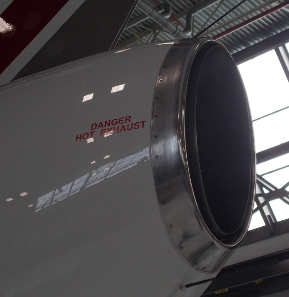
Exhaust
The exhaust system uses a muffler which sends the hot gases of the APU and part of the cool air of the tail-cone overboard. This decreases the noise of the APU exhaust. The APU muffler is found at the rear of the tail-cone.
The exhaust muffler gives a continuous outlet path for the hot combustion exhaust gases, the APU surge-valve airflow, the tail-cone compartment and generator cooling airflows while it is in operation. The Venturi effect through the exhaust muffler eductor helps the surge valve and cooling airflow to flow overboard.


12/10/15
Support Mounting
The APU support mounting is a configuration of high strength heat-treated welded stainless-steel tubular-struts. The struts attach at the APU end to the vibration isolators with bolts. Also, the struts attach at the empennage/tail end to the strut attachment fittings with bolts.
The support mounting system has an interface with Empennage/Tail Section.
The support mounting system has the components that follow:
Vibration Isolator
Three silicone-rubber vibration isolator mount-fittings are installed on three mount adapters. The mount adapters are attached to the APU gearbox at the two sides and at the top. The vibration isolators are used for the protection of the mounting struts and the tail-cone from the vibrations of the APU.
Mounting Strut
The APU is held by seven struts that attach at the aft end to the three silicone-rubber vibration isolators with bolts. Each strut consists of a stainless steel tube with machined fittings that are glued and screwed to each end.
At the forward end, these seven struts are attached to the four strut attachment fittings on the rear fuselage bulkhead with bolts. These strut attachment fittings have spherical bearings that let the struts have a small angular movement to help in the installation of the APU.
A redundant safety strut is found at the top aft-mount location on the APU and is held with a quick-disconnect pin. The safety strut is attached at the top end to the APU lift attachment fitting with bolts.
Mounting Struts Boot
Four fireproof boots are installed around the forward strut attach locations where the rear fuselage attachment fittings go through the forward firewall. A fireproof boot is also installed around the forward end of the redundant safety strut where the strut attachment fitting goes through the forward firewall.


11/29/16
Air Inlet Ducting
The air-inlet ducting system supplies airflow to the APU compressor intake for APU operation and airflow for general tail-cone compartment cooling. The system also supplies airflow which is just for generator cooling.
The air-inlet ducting system has an interface with APU Exhaust Muffler
The air-inlet ducting system has the components that follow:
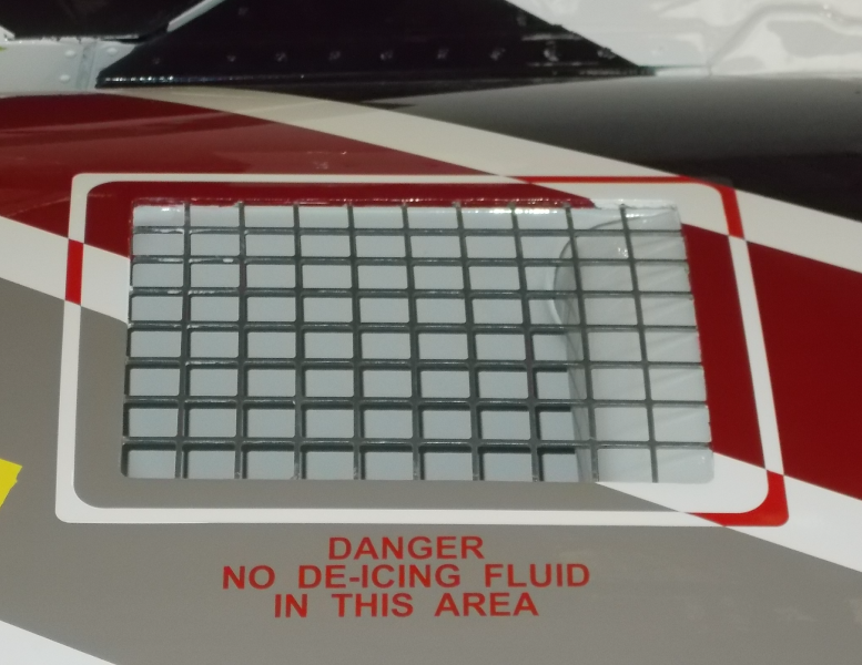
Inlet Duct
The inlet duct for the APU is found on the right side of the tail-cone.
The inlet duct is made from graphite-epoxy composite material. The outer surface of the inlet duct has a layer of fireproof paint. It is attached to the tail-cone skin by blind rivets. A rectangular stainless-steel air inlet screen with 1.0 in (2.54 cm) square holes is attached to the entry of the inlet duct. The screens pattern makes it less of a risk to have problems with ice and gives protection to the APU from large Foreign Object Debris or Foreign Object Damage (FOD).
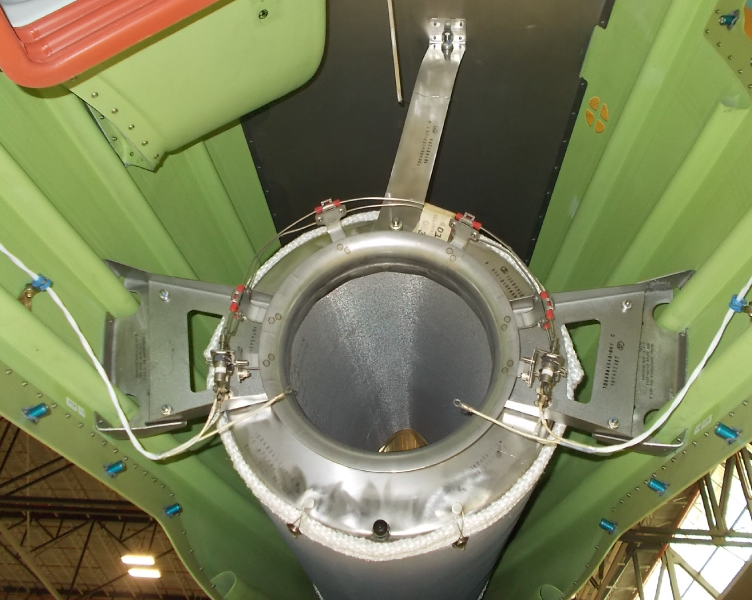
Inlet Duct Boot
An inlet duct boot connects the inlet duct to the APU inlet duct to adapt to APU movement during operation. The inlet duct boot is flexible and made from a fiberglass reinforced silicone-rubber.
The upper flange of the inlet duct boot is held by 16 bolts and two stainless-steel clamp half-frames. The 16 bolts go through the half frames and flange of the inlet duct boot to 16 anchor nuts in the inlet duct.
The lower flange of the inlet duct boot is held to the APU inlet duct by stainless-steel spring C-clips. During APU removal, the C-clips help the inlet duct boot to be disconnected quickly from the APU inlet duct.
Generator Cooling Duct
The generator cooling duct is a flexible 3.0 in (7.62 cm) diameter duct. It is made of silicone rubber that is reinforced with wire. Generator cooling ram-air is supplied from a carbon-epoxy composite NACA duct that is found at the forward lower right side of the tail-cone. The generator cooling duct is connected to the generator housing by hose clamps.
Generator Cooling Exhaust-Duct
The generator cooling air is removed from the generator housing through a generator cooling exhaust-duct. This stainless-steel exhaust duct is attached to the generator housing by a rectangular flange V-band coupling. The cooling air is used for general tail-cone cooling and goes out of the tail-cone through the APU exhaust muffler-eductor.


12/10/15
Bleed Air Ducting
The bleed-air ducting system for the APU supplies air from the load control valve (LCV) to the aircraft bleed-air ducting. The bleed air is used for the main engine start system. It is also used for the environmental control system (ECS) operation. The bleed-air ducting system has interface with the systems that follow:
- Intermediate-Pressure Bleed-Air System
- APU Exhaust Muffler
- Engine Starting System
The bleed-air ducting system includes the components that follow:
Bleed Air Duct
The APU bleed-air duct, in the tail-cone, is made in two parts from 2.5 in (6.35 cm) diameter stainless-steel tubes. The two parts are the flexible bellows duct and the short bleed-air duct. The two ducts have V-band coupling flanges at each end. Quick-disconnect V-band clamps are used to connect the LCV to the aft end of the flexible bellows duct. They also connect the forward end of the flexible bellows duct to the aft end of the short bleed-air duct, and they connect the forward end of the short bleed-air duct to the aircraft bleed-air ducting.
The flexible bellows duct connects the LCV to the short bleed-air duct. The flexible bellows in the duct let the APU have movement during operation. The short bleed-air duct goes through the forward firewall and has a bonded insulation blanket. The blanket is used to keep heat radiation to a minimum in the section forward of the firewall. During bleed air flow, the pressure and temperature in the duct can be as high as 75 psig (517.11 kPa) and 260.21 °C (500.00 °F).
Bleed-Air Check Valve
The bleed-air check valve is a 2.5 in (6.35 cm) diameter stainless-steel check-valve. The check valve is installed between the short bleed-air duct and the aircraft bleed-air ducting. It prevents the back-flow of main engine bleed-air into the APU when the APU or APU bleed air is not in operation. An O-ring is installed between the short bleed-air duct and the check valve to prevent a pressure leak. The bleed-air check valve has a notch to align it correctly with the short bleed-air duct during installation. The check valve is held in position by the forward end of the short bleed-air duct V-band-clamp connection.
Surge Valve Stub-Exhaust
The surge valve stub-exhaust, installed on the aft of the surge control valve, is made of 1.0 in (2.54 cm) diameter stainless-steel tube. There is a V-band coupling flange and clamp for the connection of the surge valve stub-exhaust to the surge control valve. The surge valve stub-exhaust points surge air to the exhaust eductor which then releases the surge air overboard through the APU exhaust muffler.

12/10/15
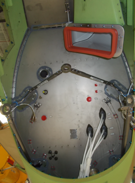
Draining
Draining of unwanted fluids from the tail-cone compartment is done through a lower drain hole in the forward tail-cone. Draining of the APU ducts is done through rigid tubing from the APU ducts. The fluid from all the drain points drain automatically and flow overboard by the effect of gravity.
The draining has the components that follow:
APU Inlet Plenum Drain
The removal of rain water or other fluids from the inlet plenum is done through the APU inlet plenum drain tube. The drain is a rigid stainless steel tube which goes through a sealed opening in the lower tail-cone access panel to drain fluid overboard.
APU Fuel Drain
The removal of fuel leakage from the fuel-pump drive seal is done through the APU fuel drain tube. The drain is a rigid stainless steel tube which goes through a sealed opening in the lower tail-cone access panel to drain fluid overboard.
Tailcone Drain Mast
The removal of rain water and other fluids from the tail-cone enclosure is done through the tail-cone drain mast. The fluids go out of the tail-cone through the tail-cone drain hole in the lower forward end of the tail-cone. The function of the drain mast is to prevent the fluids entry into the inlet duct.
APU Muffler Drain
The removal of unwanted fluid from the APU muffler is done through the APU- muffler drain tube. The drain is a rigid stainless tube which goes through a sealed opening in the lower tail-cone access panel to drain fluid overboard.


12/10/15
Operation
The APU is a self-contained power source and requires only a source of fuel and electrical power for the operation. The starting, acceleration and operation of the APU are controlled through an integral system of automatic and coordinated pneumatic systems, electro-mechanical controls, and by the APU electronic control unit (ECU).
The APU is controlled automatically from start initiation through operation at full load, following the required speeds and safe operating temperatures. When the starter motor is energized, it turns the gear train of the gearbox. The gear train turns the compressor, the oil pump, the fuel control, and turbine rotating components. As the compressor impeller and turbine rotor turn, ambient air is pulled through the inlet and compressed and then moves through a diffuser into the turbine housing assembly. From the turbine housing assembly, some of the air enters the combustion chamber. Following ignition, the APU becomes self-sustained and the heat and pressure of the ignition gases are absorbed by the turbine wheel and are changed to mechanical power to turn the gearbox gear train, compressor, and the accessories.The gearbox section supplies a 12,000 rpm clockwise rotation mounting pad for the generator unit. There is also a mounting pad for the rotary oil pump which supplies a mounting pad for the fuel control unit. The gearbox also supplies the mounting bosses for the low oil pressure switch, magnetic drain plug, oil temperature sensor, starter motor and the motional pickup transducer. The compressor air discharge is sent to the aircraft bleed system and the hot exhaust gases are sent overboard via an exhaust muffler.
The APU FAULT advisory message will show if the bleed-air check valve has a malfunction and a backflow of main engine bleed-air is sensed.
The EICAS message that follows is related to the bleed air ducting system:
| EICAS MESSAGE(S) | LEVEL (COLOR) |
|---|---|
| APU FAULT | ADVISORY (cyan) |
Operating Envelope
The envelope limiting parameters are governed by compressor inlet temperature and pressure altitude. The APU is capable of providing, simultaneously or independently, the following:
- Pneumatic air for main engine start (MES)
- Pneumatic air for environmental control system
- Generator electrical loads

APU OPERATING ENVELOPE
10/21/20
Component Location Index
| Component Location Index | |||
|---|---|---|---|
| IDENT | DESCRIPTION | LOCATION | IPC REF |
| - | AUXILIARY POWER UNIT (APU) | ZONE(S) 320 | 49-11-01 |
| - | MOUNTING STRUT BOOT | ZONE(S) 320 | 49-12-05 |
| - | INLET DUCT | ZONE(S) 320 | 49-15-01 |
| - | INLET DUCT BOOT | ZONE(S) 320 | 49-15-05 |
| - | BLEED AIR DUCT | ZONE(S) 320 | 49-16-01 |
| - | BLEED-AIR CHECK VALVE | ZONE(S) 320 | 49-16-03 |