


01/04/16
Overview
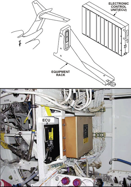
The APU uses a computer-based electronic control unit (ECU) to control the APU and provide an interface with the aircraft and its subsystems.
The ECU is installed in an equipment rack in the aft equipment compartment.
The ECU control system incorporates a built-in test equipment feature that ensures safe operation of the APU and initiates protective shutdown.
The Challenger 350 flight deck provides bleed-air system, electrical panel, APU control and fire system, and APU panel hardware discrete signals to interface with the APU ECU. The maintenance diagnostics computer (MDC) and EICAS interface with the ECU, using ARINC 429 to display fault data and operation status. Additionally, the remote switch located on an external services panel interfaces with the ECU for APU emergency shutdown.
The flight or maintenance crew start and stop the APU with a switch on the APU control panel. The location of this panel is at the rear of the flight compartment center pedestal, on the right side. There is a switch with the legends OFF, RUN, and START shown at the three possible positions. The multi-function displays show the applicable warnings and cautions, status, temperature and speed of the APU.
The engine control system uses logic to calculate the control decisions for the airborne auxiliary power system. Inputs to the auxiliary power unit (APU) electronic control unit (ECU) come from the inlet temperature sensor, the speed sensor, the exhaust gas temperature sensor and different aircraft systems. The APU ECU then sends the applicable control signals to specified APU components and other aircraft systems. The operation of these components causes the APU to start, to adjust the operation, or to shut down.

10/26/16
APU Electronic Control Unit (ECU)
The APU ECU is installed in an equipment rack in the aft equipment compartment. All electrical signal connections to the aircraft and the APU go through an ARINC connector installed on the rear panel of the APU ECU. The APU ECU is an electrically operated, computer controlled, digital controller.
The aircraft power energizes the APU ECU internal dc power-supply, which supplies power to the APU ECU computer and the output load drivers. Approximately three seconds after the APU ECU is energized, it transmits ARINC signals to the EICAS display panel.
The APU ECU also has interfaces directly with the electrical and electronic components in the airborne auxiliary-power system. The interfaces for the APU ECU, by the ARINC data bus or directly connected, are all through its ARINC electrical connector. The APU ECU also has interfaces with other systems and components, which include:
- The L ESS BUS (the primary source of power for the APU ECU)
- The R MAIN BUS (the secondary source of power for the APU ECU)
- The R BATT BUS
- The EICAS display panel in the flight compartment
- The air conditioning and bleed-air control panel in the flight compartment
- The APU start auxiliary-power-contactor
- The auxiliary generator control-unit
- Weight-on-wheels signal (from the proximity-sensor electronic unit)
- External power control panel
- Engine control panel (for APU fire).
Speed Sensor
The speed sensor measures the APU speed. It has a permanent magnet core with one coil. The sensor, which is installed in the APU gearbox, is not adjustable and a calibration is not necessary. It operates when a spur gear in the gearbox turns, but it does not touch the spur gear.
The speed sensor uses magnetic properties to cause an ac output-voltage signal. This signal changes as the spur gear teeth move through the magnetic field of the speed sensor. The signal value is in proportion to the speed of the spur gear. The APU ECU reads the frequency of the changes in the ac output-voltage signal. It uses this data to monitor and control the APU speed during the ignition/start sequence and in all modes of APU operation. The sensor will continue to operate if only one coil fails. Although, if both coils fail, the APU ECU will cause a shutdown and prevent operation of the APU.


Inlet Temperature Sensor (T2)
The inlet temperature sensor (T2) is mounted on the front left side of the inlet plenum as viewed from the front. The T2 sensor detects ambient (compressor inlet) air temperature.
The T2 sensor is an electrical resistance thermal device (RTD) which uses resistance proportional to temperature. This signal is continuous, thus allowing actual temperatures to be monitored during APU operation. A failure of the T2 sensor does not cause an APU protective shutdown, but posts an MDC message. During an inlet temperature sensor (T2) failure, the ECU receives a secondary T2 input through the ARINC bus interface, from the aircraft input-output concentrator (IOC). If there are no inputs available from the ARINC interface, then the ECU defaults the T2 signal to –40°F, allowing the APU to continue operation.


01/04/16
EGT Thermocouple
The thermocouple consists of chromel-alumel wires welded together within a single probe mounted on a non-adjustable flange on the turbine housing. The thermocouple monitors the exhaust gas temperature and provides a signal to the ECU. The ECU uses these signals to provide EGT flight deck indication, fuel trim schedules, and the LCV modulation for over temperature control and initiates over temperature shutdowns.
The EGT thermocouple measures the continuous temperature from 316 to 704°C (600 to 1,300°F). The EGT thermocouple also measures sudden temperatures as high as 1,093°C (2,000°F).
EGT is required for all phases of APU operation and is continually monitored by the ECU. During prestart BITE, the ECU checks the thermocouple for an input range of –73 to 1,093°C (–100 to 2000°F). If the thermocouple input signal is out of range, the ECU will inhibit the start (ground only).
If the sensor becomes defective during flight, the APU will continue to operate and a message shown on the EICAS display to identify the fault condition.

Hour Meter (Time Totalizer)
The hourmeter (time totalizer) is mounted adjacent to the fuel SOV, on the left front side of the APU. The time totalizer is a digital counter that sends accumulated hours to the ECU.
At 95% rpm, the ECU provides an excitation signal to the time totalizer, activating the internal counter circuity. At APU shutdown, the time totalizer is deactivated by the ECU. During every prestart BITE, the ECU checks its accumulated hours against the stored value in the time totalizer. If the stored value differs from the ECU stored value, the ECU will update its hours to equal the time totalizer. At the end of each APU run, the ECU reads and stores the accumulated hours.
The ECU sends the accumulated operating hours through the ARINC 429 bus to the MDC system.

01/04/16
Operation
The hardware and the software for the APU ECU have built-in test (BIT) functions. The BIT equipment monitors the APU ECU internal operation and the performance of the components which the APU ECU controls. It also transmits the BIT error and fault condition data. The APU ECU uses the data to cause an applicable display on the EICAS display panel. Temperatures shown on the display panel are in degrees Celcius. All BIT errors and data on unserviceable components are also transmitted to the maintenance diagnostics computer (MDC) through the ARINC data bus.
If the BIT equipment finds a dangerous condition, the APU ECU immediately causes a shutdown for the protection of the APU. The APU ECU can cause a shutdown for protection during the start sequence, or during APU operation (in all modes, with or without a load). After the APU ECU finds the specified fault condition and starts the APU shutdown, no more BIT functions are started. During flight, the APU ECU logic lets the APU continue to operate with some conditions that can cause a protective shutdown when on the ground. During flight conditions, the APU ECU causes the applicable fault condition data, caution or warning to be shown on the EICAS display panel.
Shutdowns for the protection of the APU occur when the conditions are as follows:
- The DC power is not available*
- The APU ECU is defective*
- There is no signal from the EGT
- There is a fire*
- There is a flow of gas in the opposite direction
- There is no protection against an overspeed condition*
- The oil temperature is too high
- The oil pressure is too low
- There is no acceleration
- There is no flame
- There is an overspeed condition*
- There is an overtemperature condition
- The speed signal is not available
- The oil temperature sensor is defective
- The surge control valve is defective.
*Note:
These items are category 1 fault conditions. These are the only conditions which cause an automatic shutdown in flight. The remainder of the fault conditions are shown on the EICAS display in flight but the APU continues to operate. All fault conditions listed above cause an automatic shutdown when the aircraft is on the ground.
Inputs to the APU ECU are discrete signals from other aircraft systems, analog and discrete signals from components in the APU and digital data from the ARINC 429 data bus. These include:
- The APU EGT sensor
- Low oil-pressure switch
- The inlet temperature (T2) sensor
- The speed sensor
- The oil temperature sensor
- Load control valve (LCV) position signal
- The hourmeter
- The APU FIRE switch on the Engine control panel
- The aircraft bleed command signal (LCV OPEN)
- Start contactor voltage.
The aircraft interface signals that follow are given to the APU ECU for APU operation:
- The APU OFF/RUN/START switch on the APU control panel
- Weight on wheels (WOW) signal from the proximity sensor electronic unit (PSEU)
- Generator ready-to-load (RTL) signal to the generator control unit (GCU)
- APU start contactor command signal.
The APU ECU outputs are discrete signals to the applicable components in other aircraft systems, analog and discrete signals to applicable components in the APU and digital data to the ARINC 429 data bus. These include:
- Ignition unit command signal
- LCV position command signal
- Surge valve on/off signal
- Aircraft fuel valve command signal
- Fuel control shutoff valve solenoid command signal
- The LCV position command signal
- The digital data to the ARINC data bus.
The APU OVERTEMP warning message will show when an APU EGT overtemperature has been sensed. An APU EGT overtemperature condition occurs at 718 °C (1,325°F) when the APU is at 100%.
The APU OVERSPEED caution message will show when an APU overspeed occurs. An APU overspeed condition occurs when the APU speed goes to 63,436 rpm (17,600 Hz) equivalent to 106% of the nominal speed.
The APU SHUTDOWN advisory message will show when the APU ECU has shutdown the APU for protective reasons.
The EICAS messages that follow are related to the engine control system:
| EICAS MESSAGE(S) | LEVEL (COLOR) |
|---|---|
| APU OVERTEMP | WARNING (red) |
| APU OVERSPEED | CAUTION (amber) |
| APU SHUTDOWN | ADVISORY (cyan) |


Display and Indicating
The EICAS status displays for the flight crew are APU speed (in rpm), APU exhaust gas temperature (EGT), and APU START (during APU start cycle to 95% +4 sec).
Once the APU MASTER switch is rotated to the RUN position and the ECU has completed pre-bite test, the ECU transmits EGT and rpm status information to the EICAS display.
The APU EGT indication displays as follows:
- Unit of measurement is °C
- Normal indication green
- Unknown EGT, indication changes to magenta
- Limit indicated in red (varies with altitude)
- The APU RPM indication displays as follows:
- Unit of measurement is %
- Normal indication green
- Unknown speed indication changes to magenta
- 108% (overspeed) indicated in red

01/04/16
System Interface
The engine control system has interfaces with the systems that follow:
- Engine Fuel System
- Bleed Air Supply
- Indicating
10/21/20
Component Location Index
| Component Location Index | |||
|---|---|---|---|
| IDENT | DESCRIPTION | LOCATION | IPC REF |
| A39 | APU ELECTRONIC CONTROL UNIT (ECU) | ZONE(S) 320 | 49-61-01 |
| TC2 | EXHAUST GAS TEMPERATURE (EGT) SENSOR | ZONE(S) 320 | 49-61-05 |
| RT02 | INLET TEMPERATURE SENSOR | ZONE(S) 320 | 49-61-09 |
| MT116 | SPEED SENSOR | ZONE(S) 320 | 49-61-13 |
| A174 | AUXILIARY POWER UNIT (APU) HOURMETER | ZONE(S) 320 | 49-70-01 |