


12/21/15
Overview
Small items of cargo and baggage can be put into the aircraft through a baggage door on the left side of the fuselage between FS641.75 and FS669.76. This door is not used as an emergency exit. It is an inner and an outer skin made stronger with beams, frames and intercostals.
The width of the baggage door opening is 24 inches (61 cm) and the height is 42 inches (109 cm). The door is a plug-type which opens into the rear of the passenger compartment. Balance springs help the operator to lift the weight of the door as the door moves up on tracks. There is an internal handle and an external handle. A vent flap makes sure that remaining cabin air pressure can decrease to zero before the door opens.
The baggage door has an interface with the Proximity-Sensor Electronic Unit.

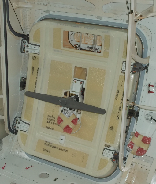
Baggage Door
The baggage door is a plug type door. When the baggage door is in the closed position, four door stop fittings installed on the baggage door engage four fuselage stop fittings. Two door stop fittings are on the forward side and two are on the aft side of the door. The pressurization loads are absorbed by these door stop fittings and the door latch mechanism. These door stop fittings include rollers which move in two tracks. The baggage door includes a door latch mechanism to open and close the door. There is an inner and an outer handle installed to open and close the door.
When the door opens, it moves in and up into a stowed position. There is a vent door at the top of the baggage door. The vent door is connected to a bell crank by a pushrod. The bell crank is controlled by the inner or outer handles. When the handles are turned to open the baggage door, the vent door opens to release remaining air pressure in the cargo area.
There are two springs connected to the vent door which help to open it when there is remaining air pressure. The vent door will not close if the baggage door is not fully closed and the handle is not stowed in the locked position. This prevents the start of pressurization unless the baggage door is closed and locked.
Two proximity sensors are installed on the baggage door. The first proximity sensor is installed on a support bracket in the inner handle housing. The other door proximity sensor is installed in the forward latch fitting on the fuselage frame. It is in a housing which has a spring to adjust for all the possible backlash of the forward latch mechanism.


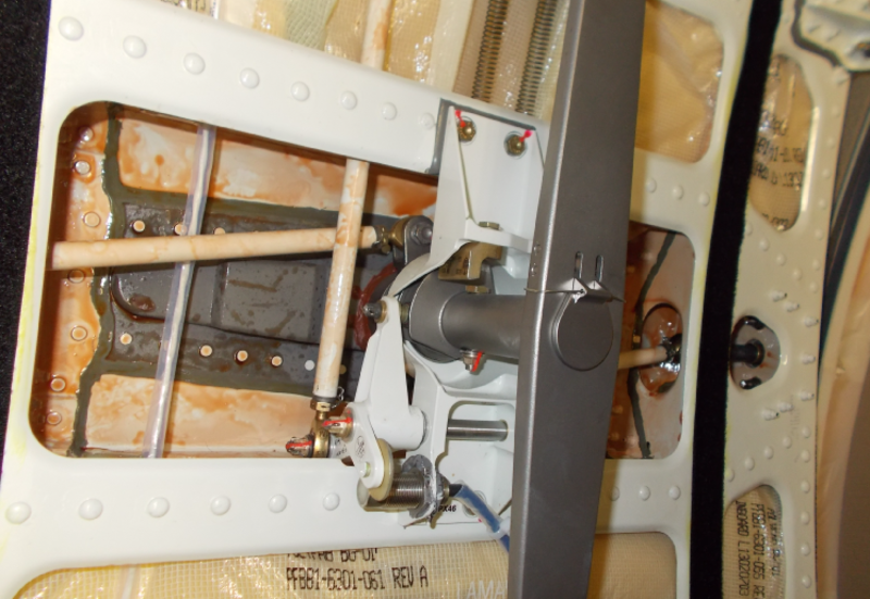
Baggage Door Latch Mechanism
The baggage door latch mechanism holds the baggage door in the closed position. It is installed between the inner and the outer skins of the door structure. The door can open from the internal side or external side of the aircraft. When the latch mechanism operates, two bolts extend from the forward and aft edges of the door into latch fittings on the adjacent fuselage frames.
The baggage door latch mechanism includes a handle, an overcenter lock-assembly, and pushrods. The baggage door handle attaches at the central line of the baggage door. The handle has an outer handle and an inner handle that come as one assembly. The handle housing attaches to the outer skin of the baggage door.
The outer handle has a button to release it and a key lock. The inner handle also has a button to release it and a cover for protection which prevents it from accidental operation during flight. The outer handle fits in the handle housing when it is aligned with the recess and then pushed. The handle connects to the outer handle has a button to release it and a key lock. The inner handle also has a button to release it and a cover for protection which prevents it from forward and aft latch pushrods. The handle also moves a bell crank that connects to the vent door pushrod.
The overcenter lock-assembly has a compression spring, a male overcenter link, and a female overcenter link. The compression spring holds the latch mechanism in the open or closed position. The forward and aft latch pushrods connect the bolts to the crank of the handle. The handle turn direction can operate the latch mechanism to extend or retract the bolts. One more pushrod connects the vent door to the bell crank which is attached to the structure of the door. This bell crank is connected to the inner handle. When the inner handle is pushed or pulled, it moves the bell crank. Then the bell crank operates the vent door pushrod which opens or closes the vent door.


Baggage Door Seal
The baggage door seal is installed around the outer edge of the door. It is attached to the baggage door with seal retainers. The seal prevents air leakage around the baggage door when the aircraft pressurizes. Pressurized air from the cargo area pushes the seal against the adjacent structure.
12/21/15
Baggage Door Balance Springs
There are two baggage door balance springs attached to the fuselage structure above the baggage door. Each balance spring has a spring wound to help lift the baggage door. A cable from each balance spring is attached to the door at the top doorstop fitting near the roller assembly. The cables wind on pulleys when the door opens and lifts it. A detent spring is installed in the forward track to hold the door in the fully open position if one cable is defective.

Baggage Door Tracks
The forward track is attached to the fuselage frame. The aft track is attached to the fuselage bulkhead structure. The tracks have channels in which the rollers on the doorstop fitting can move. The two tracks have a track doorstop. There is a detent spring installed only in the forward track. This spring helps to hold the door fully open.


Operation
To open the baggage door from the outside, the release button is pushed which releases the outer handle from the handle housing. A turn of 90° counterclockwise of the handle releases the latch mechanism. The door is pushed in and then up until it is in the fully open position. The door engages the detent spring and stays open.
To close the baggage door from the outside, the door must be pulled down until it is not engaged by the detent spring. Then the door is lowered fully and pulled to engage the fuselage stop fittings. A turn of 90° clockwise of the handle engages the latch mechanism. When the door is fully latched and the handle is aligned with the recess, then the handle is pushed and moves in the handle housing. When the outer handle is pushed fully, the release button latches the door closed. Then the handle can be locked with the key.
To open the baggage door from the inside, the cover on the inner release button must be lifted and the button must be pushed to release the outer handle from the handle housing. A turn of 90° clockwise of the inner handle releases the latch mechanism. The door is pulled in and then up until it is in the fully open position. The door engages the detent spring and stays open.
To close the baggage door from the inside, the door must be pulled down until it is not engaged by the detent spring. Then the door is lowered fully and pushed to engage the fuselage stop fittings. A turn of 90° counterclockwise of the inner handle engages the latch mechanism. When the door is fully latched, the inner handle is pulled until the outer handle moves in the handle housing. When the outer handle is pulled fully, the release button latches the door closed.
Two sensors monitor that the baggage door is closed and locked. The sensors monitor the door position and send signals to the proximity sensor electronic unit (PSEU). From the received signals, the PSEU sends a signal to the engine indicating and crew alerting system (EICAS).
The door handle proximity sensor senses the handle stowed position (door handle locked). The other proximity sensor senses the fully latched position of the door (door closed).
The sensors make a two signal configuration. This configuration lets the PSEU to monitor a sensor that could sense incorrectly when near its target. If the PSEU agrees that the signal is an error, it will not send a signal to the EICAS. If the PSEU agrees that the signal is correct then it sends a signal to the EICAS. This will show the CARGO DOOR message on the EICAS display, flash the master warning/caution switch/light, and operate the aural warning.