


Overview
The horizontal stabilizer gives pitch trim control of the aircraft. The horizontal stabilizer is installed at the top of the vertical stabilizer.
The horizontal stabilizer is a one-piece airfoil-shape structure. It moves about the lateral axis on two support fittings on the top of the vertical stabilizer. A screw-type trim actuator, installed at the top of the vertical stabilizer, adjusts the angle of attack for the horizontal stabilizer. The left and right elevators are attached to the trailing edge of the horizontal stabilizer for control about the lateral axis.

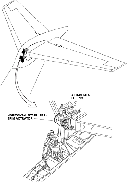
Horizontal-Stabilizer Trim-Actuator Attachment-Fitting
The horizontal stabilizer has two attachment fittings attached to the front spar of the horizontal stabilizer. The fittings are aluminum alloy machined-parts and are the attachment point for the horizontal stabilizer-trim actuator.
Horizontal-Stabilizer Access-Panel
The horizontal stabilizer has six access panels which are made from aluminum-alloy. There are two small panels on the top and two small panels on the bottom of the horizontal stabilizer. Those give access to the elevator linkage for maintenance.
Note:
The four small access panels extend longer than the trailing edge of the horizontal stabilizer but there is no interference with the elevators.
Also, there are two large panels on the bottom of the horizontal stabilizer which give access to the elevator power control-unit (PCU) for maintenance.

Horizontal-Stabilizer Visor Fairings
The top and bottom visor fairings are installed on the sides of the horizontal-stabilizer center box to make a weather seal. The edges of the top and bottom visor fairings have rubber strips which rub against the side middle-fairings when the horizontal stabilizer moves. Rubber seals attached to the horizontal-stabilizer leading edges at the inboard ends complete the weather seal.

10/21/20
Component Location Index
| Component Location Index | |||
|---|---|---|---|
| IDENT | DESCRIPTION | LOCATION | IPC REF |
| - | HORIZONTAL-STABILIZER TRIM-ACTUATOR ATTACHMENT FITTING | ZONE(S) 351/361 | 55-10-01 |
| - | LOWER ELEVATOR-LINKAGE ACCESS-PANEL | ZONE(S) 351AB/361AB | 55-10-05 |
| - | UPPER ELEVATOR-LINKAGE ACCESS-PANEL | ZONE(S) 351AT/361AT | 55-10-05 |
| - | ELEVATOR POWER-CONTROL-UNIT (PCU) ACCESS-PANEL | ZONE(S) 351BB/361BB | 55-10-05 |
| - | LOWER HORIZONTAL-STABILIZER VISOR FAIRINGS | ZONE(S) 346ALZ/346ARZ | 55-10-15 |
| - | UPPER HORIZONTAL-STABILIZER VISOR FAIRINGS | ZONE(S) 346BLZ/346BRZ | 55-10-15 |