


12/29/15
Overview
The engine nacelle electrical harnesses are attached to the pylon interface firewall with connectors. The harnesses in the nacelle electrically connect components on the engine to the aircraft systems.
There are three primary electrical harnesses in each nacelle: the full authority digital electronic control (FADEC) electrical harness, the generator control harness and the fire detection harness.

12/29/15
Full Authority Digital Engine Control (FADEC) Electrical Harness
The FADEC electrical harness carries signals between the electronic control unit (ECU) and the aircraft systems. These signals control and operate the engine systems and supply data for display in the flight compartment. The harness is a loom of screened wires with four connectors. The harness is connected to the pylon interface, ECU, engine internal wiring harness, and thrust reverser. Clips attach the harness to the engine between the forward engine mount frame and the thrust reverser. Spring clips are installed around the top of the forward engine mount frame and at the thrust reverser interface. Grommets attached to the harness are installed in the spring clips.


12/29/15
Generator Control Harness
The generator control harness carries signals to and from the generator. These signals control and operate the generator and supply data for display in the flight compartment. The harness is a loom of four screened wires with two connectors at each end. The harness is connected to the pylon interface and the generator. Grommets attached to the harness are installed in the spring clips between the fan inlet housing and the forward outer fan duct. P-clips attach the harness to the bottom of the forward outer fan duct between the generator and the pylon interface.

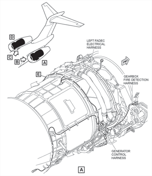
Fire Detection Harness
The fire detection harness assembly has the following three fire detection harnesses:
- Gearbox
- Zone 2
- Pylon
The harnesses connect the sensing elements of the engine fire detection system. The gearbox fire detection harness connects the wet bay sensing element to the gearbox sensing element. The zone 2 harness connects the gearbox sensing element to the zone 2 sensing element and the zone 2 sensing element to the pylon fire detection harness. The pylon fire detection harness connects the zone 2 fire detection harness to the pylon sensing element.
The fire detection harnesses are installed around the engine with spring clips and P-clips which are attached to the engine and the outer fan duct. The harnesses have eye-end connectors attached to the electrical connectors on the sensor wires with screws, nuts and washers. The zone 2 fire detection harness and pylon fire detection harness are connected by an electrical connector.


12/29/15
System Interface
The engine electrical harnesses interface with the following systems/components:
- Engine Fire Detection System
- Fuel Control System
- Fuel Indication System
- Full-Authority Digital Engine Control (FADEC) System
10/22/20
Component Location Index
| Component Location Index | |||
|---|---|---|---|
| IDENT | DESCRIPTION | LOCATION | IPC REF |
| - | LEFT ENGINE ELECTRONIC CONTROL UNIT (ECU) A HARNESS | PANEL(S) 432BT/BB ZONE(S) 430 |
71-50-05 |
| - | RIGHT ENGINE ELECTRONIC CONTROL UNIT (ECU) A HARNESS | PANEL(S) 442BT/BB ZONE(S) 440 |
71-50-05 |
| - | LEFT ENGINE ELECTRONIC CONTROL UNIT (ECU) B HARNESS | PANEL(S) 432BT/BB430 | 71-50-05 |
| - | RIGHT ENGINE ELECTRONIC CONTROL UNIT (ECU) B HARNESS | PANEL(S) 442BT/BB ZONE(S) 440 |
71-50-05 |
| - | LEFT ENGINE GENERATOR CONTROL ELECTRICAL HARNESS | PANEL(S) 432BB ZONE(S) 430 |
71-50-15 |
| - | RIGHT ENGINE GENERATOR CONTROL ELECTRICAL HARNESS | PANEL(S) 442BB ZONE(S) 440 |
71-50-15 |
| - | LEFT ENGINE ZONE 2 FIRE DETECT ELECTRICAL HARNESS | PANEL(S) 432BT/BB ZONE(S) 430 |
71-50-19 |
| - | RIGHT ENGINE ZONE 2 FIRE DETECT ELECTRICAL HARNESS | PANEL(S) 442BT/BB ZONE(S) 440 |
71-50-19 |
| - | LEFT ENGINE PYLON FIRE DETECT ELECTRICAL HARNESS | PANEL(S) 432BT/BB ZONE(S) 430 |
71-50-23 |
| - | RIGHT ENGINE PYLON FIRE DETECT ELECTRICAL HARNESS | PANEL(S) 442BT/BB ZONE(S) 440 |
71-50-23 |
| - | LEFT ENGINE GEARBOX FIRE DETECT ELECTRICAL HARNESS | PANEL(S) 432BT/BB ZONE(S) 430 |
71-50-27 |
| - | RIGHT ENGINE GEARBOX FIRE DETECT ELECTRICAL HARNESS | PANEL(S) 442BT/BB ZONE(S) 440 |
71-50-27 |