


01/12/16
Overview
The temperature indicating system supplies the temperature of the low-pressure (LP) turbine gases to the flight compartment, on the engine indicating and crew alerting system (EICAS) displays.
The system measures the temperature of the low-pressure turbine gases. The system sends a related electrical signal to each ECU. From this temperature data, the ECU calculates the interturbine temperature (ITT). The ITT is the temperature of the gases that go into the LP turbine. The temperature data is also supplied to the full authority digital engine control (FADEC) system for engine control functions. The temperature indicating system includes the temperature sensing subsystem.
The temperature sensing system has eight exhaust gas temperature (EGT) probes that measure the interturbine temperature (ITT), and one Tt2 sensor that measures the compressor inlet temperature. The eight EGT probes supply the temperature measurement to the ECUs. Each electronic control unit (ECU) uses this data and other engine parameters to calculate an average interturbine temperature (ITT) of the engine. The flight compartment shows the ITT on the engine indicating and crew alerting system (EICAS) display. A Tt2 sensor measures the engine inlet total air temperature. The controlling ECU uses this engine inlet total air temperature for engine power control.
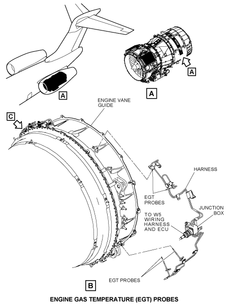
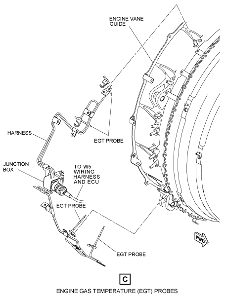
Exhaust Gas Temperature Probes
There are eight exhaust gas temperature (EGT) probes that are thermocouples in the temperature sensing system. Four EGT probes connect to each ECU. The ECUs use these signals to prevent overtemperature of the turbine during the engine start procedure and in usual operation.
The EGT temperature data from each ECU is the electrical average of the four EGT probes. Two ECUs share their EGT temperature data through the cross-channel data link. The temperature data through this link is the average of the eight EGT probes. The ECUs use this data and other engine parameters to calculate an interturbine temperature (ITT) of the engine. This ITT data is shown on the primary flight display (PFD).
There are two harnesses connected in parallel, each with four EGT probes and a junction box to make up one harness. The EGT probes are made of alumelchromel thermocouples that can measure temperatures up to 966°C (1,770 F).
The junction box of each harness connects to an ECU. The output of each junction box is the electrical average of the four thermocouple probes. The EGT probes are installed into eight ports at the exhaust guide vane nozzle. The access panels on the rear inner fan duct gives accesses the EGT thermocouples and their related harnesses.


Inlet Temperature (Tt2) Sensor
The Tt2 sensor is a platinum resistance temperature unit with a hermetic seal. It senses the inlet total air temperature of the engine and signals the ECUs for engine power control. The Tt2 sensor is at the 12 o’clock position of the engine inlet. A wire lead and a connector are part of the Tt2 sensor. The Tt2 sensor has two temperature sensitive resistance components and a heat element for anti-ice.


01/12/16
System Operation
The eight EGT probes at the exit guide vanes sense the temperature of the exhaust gases at the low pressure (LP) turbine. The temperature signals are sent to the ECUs. Each ECU receives a temperature input which is an electrical average of four EGT probes. Through the cross-channel data link, the ECUs share the EGT signals with each other. The ECUs send the EGT signals to the PFD with a temperature reading that is an average of all eight EGT probes.
For engine temperature protection, the ECUs use the average of the EGT signals to calculate an ITT signal with a temperature limit. The ECUs calculate an ITT limit of 621°C (1,149.8 F) for an engine start, and another ITT limit of 949.3°C (1,740.7 F) for engine operation.
The two ITT limits prevent an engine temperature that gets too hot, and the calculation is based on N1 and N2 inputs. When the engine speed is less than or equal to 40% N2, the ECUs calculate an ITT value equal to the average EGT value. If the N1 and N2 signals are incorrect, ITT is equal to EGT.
The EICAS messages L ENGINE EXCEEDANCE and R ENGINE EXCEEDANCE will show on the PFD when the ITT temperature sensed by the ECU is more than the approved limits that follows:
- 955 ºC (1,751 ºF) in APR and TO
- 950 ºC (1,742 ºF) for all other ratings
Note:
The 955 ºC (1,751 ºF) limit for APR and TO is held for 5 minutes when both engines are operational and the throttle is in the TO or APR setting and 10 minutes in an OIE condition when the throttle is in the TO or APR setting. When that timer expires the limit returns to 950 ºC (1,742 ºF).
The Tt2 sensor on each engine senses the engine inlet total air temperature and sends this signal to the ECU. The ECU uses this signal for the engine power control.
The Tt2 sensor has its own electrical heat element for anti-ice. This heat element receives 28 VDC power through the use of the ENG L or R pushbutton annunciator (PBA) on the ANTI-ICE control panel.
When ice condition occurs on an engine, a ICE DETECTED caution message shows on the PFD. When the pilot pushes the ENG L or R PBA on the ANTI-ICE control panel, the cowl anti-ice solenoid de-energizes. The cowl anti-ice valve opens. At the same time the PBA is pushed, the Tt2 sensor heat element receives a 28 VDC power to start its own anti-ice.
There is a cross-channel data link between the ECUs on the same engine. The cross-channel data link lets each ECU share the Tt2 and EGT data with each other. The cross-capable discrete is a data link between the same channel ECU of the two engines. The cross-capable discrete link lets the same channel ECU from the two engines share the data with each other.
The EICAS messages that follow are related to the temperature sensing system:
| EICAS MESSAGES | LEVEL (COLOR) |
|---|---|
| L ENGINE EXCEEDANCE | WARNING (red) |
| R ENGINE EXCEEDANCE | WARNING (red) |


01/12/16
System Interface
The temperature sensing system interfaces with the component that follows:
- Electronic Control Unit (ECU)