


Overview
The vibration sensor monitors the engine vibration level and sends its output signal to the two electronic control units (ECUs). The two ECUs change this signal and send it to the engine indicating and crew alerting system (EICAS) display in the flight compartment.
01/12/16
Vibration Sensor
The vibration sensor is a piezo-electric, low-impedance transducer which measures the engine vibration level. The vibration sensor gives a signal output in the same proportion as the intensity of the engine vibration.
The vibration sensor is attached to the engine front frame, at the 12 o’clock position of the fan duct. Its output signal is used by two ECUs and by the ground analyzer equipment for fan trim balancing.


01/12/16
System Operation
When the vibration occurs in the engine, the vibration sensor piezo-electric crystal makes an electrical signal in proportion to the vibration. The vibration sensor sends this electrical signal as inputs to the left and right electronic control units (ECUs). The ECUs receive this electrical signal and send it to the EICAS display in the flight compartment.
On the EICAS display, a yellow VIB flag shows below the N1 display of the applicable left or right engine. The yellow VIB flag shows when the applicable engine vibration monitoring unit value is more than the set value of 0.78 ips (inch/second). Then the applicable L(R) ENGINE VIBRATION caution message also shows on the EICAS display. If all the sources of the applicable engine vibration measurement have been sensed with a fault condition, the applicable L(R) ENG VIBRATION FAIL advisory message shows.
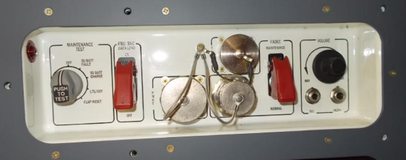
The vibration sensor also sends its electrical signal to the maintenance panel. The maintenance panel is on the equipment rack, in the cabin, on the left side of the passenger entrance. Fan trim balancing on ground is done with a connection of a ground analyzer equipment to the FADEC connector on the maintenance panel.
The EICAS messages that follow are related to the vibration sensing system:
| EICAS MESSAGES | LEVEL (COLOR) |
|---|---|
| L ENGINE VIBRATION | CAUTION (amber) |
| R ENGINE VIBRATION | CAUTION (amber) |
| L ENG VIBRATION FAIL | ADVISORY (cyan) |
| R ENG VIBRATION FAIL | ADVISORY (cyan) |


01/12/16
System Interface
The vibration sensing system interfaces with the component that follow:
- Electronic Control Unit (ECU)