Overview
The collector/nozzle collects bypass air from the fan, exhaust gases from the turbine, and sends the gas and the air overboard. The collector/nozzle controls the fan bypass duct and turbine exit areas. The collector/ nozzle control increases the engine performance and changes the remaining turbine thermal energy to thrust. The mixture of warm and cold air increases the jet speed while it decreases the higher core speed. This causes a better thrust, decreases noise, and uses fuel more efficiently. The collector/nozzle decreases engine noise through acoustic treatment.
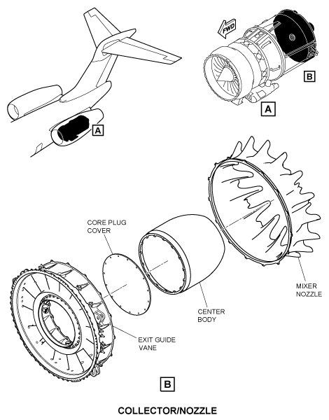
The collector/nozzle is part of the exhaust system of the engine which controls engine airflow to give thrust. The collector/nozzle is attached as a unit at the forward interface to the exit guide vane. The collector/nozzle has a mixer nozzle, a center body, and core plug cover. The mixer nozzle is a circular structure with a flange at the front end. The exhaust mixer nozzle and center body make an annular duct through which the exhaust gases flow out of the engine core. The mixer nozzle mixes the bypass air from the fan with the exhaust gases from the turbine before it flows out rearward of the engine. The collector/nozzle has the exhaust mixer nozzle subsystem.
Exhaust Mixer Nozzle
The exhaust mixer nozzle is part of the exhaust system of the engine. The exhaust mixer nozzle is attached as a unit at the forward interface to the exit guide vane. It mixes the airflow from the engine core and the bypass duct to give thrust. The mixture of warm and cold air increases the jet speed while it decreases the higher core speed. This causes a better thrust, decreases noise, and uses fuel more efficiently.
Mixer Nozzle
The exhaust mixer nozzle is a circular structure with a flange at the front end. The rear end of the exhaust mixer nozzle has 16 lobes. The mixer nozzle mixes the fan bypass air and core flows together before the exit of the engine.
Center Body and Core Plug Cover
The center body is an open end cone with an internal flange at the front end. This flange attaches to the core plug cover. The exhaust mixer nozzle and center body supply an annular duct through which exhaust flows from the engine core. The center body has the shape of a truncated cone for decreased weight and easy installation. The center body has an internal plate insulate the aft engine from hot engine exhaust. The exhaust components are Inconel for heat resistance and extended part life.
The core plug cover is an internal plate that attaches to the center body. The core plug cover supplies the necessary insulation to the aft engine from hot engine exhaust.