


Overview
The thrust reverser actuating system moves and controls the pivot doors of the thrust reverser into the correct position to supply forward or reverse thrust. There are two positions for the pivot doors, the stowed-and-locked position (forward thrust) and deployed position (reverse thrust).
When the pivot doors are in the stowed-and-locked position, the exhaust gases point rearward. In this configuration, the power plant gives forward thrust for takeoff and flight. When the pivot doors are in the deployed position, the exhaust gases point forward.
In this configuration, the power plant gives reverse thrust to decrease the aircraft speed on the ground. The actuating system is hydraulically operated and electrically controlled.
Thrust Reverser Isolation Control Unit
There are two thrust reverser isolation control units (ICUs) in the aft equipment compartment. They are found at FS694.00 at the top of the brackets for the left and right hydraulic systems. The ICU controls the hydraulic pressure to the directional control unit of the thrust reverser actuating system. The ICU has an internal solenoid valve, isolation valve, pressure switch, and microswitch. The ICU also has an inhibit lever.
When energized, the solenoid valve lets hydraulic pressure from the left and right hydraulic systems move the isolation valve to the supply position.
When de-energized, the solenoid valve isolates the hydraulic pressure from the left and right hydraulic systems which moves the isolation valve to the stop position. The isolation valve then supplies or stops the hydraulic pressure to the directional control unit of the thrust reverser actuating system.
The pressure switch transmits a signal to the ECU to give an indication when the downstream pressure of the isolation valve is high.
The inhibit lever mechanically prevents the isolation valve from untimely activation of the system pressurization.
When the inhibit lever is in the OPEN position, the isolation valve can operate as usual. When the inhibit lever is in the CLOSE position, it blocks the isolation valve in the stop position to prevent its operation. The inhibit lever is kept in the OPEN or CLOSE position by a quick-release pin.
A micro-switch in the ICU signals the ECU when the inhibit lever is moved to the CLOSE position. The ICU is usually put to the CLOSE position during maintenance operation.

Thrust Reverser Directional Control Unit
The thrust reverser directional control unit correctly sequences the primary locks and the actuators. The thrust reverser directional control unit also configures the pressure conditions of the thrust reverser actuation system, which moves the pivot doors to the deployed position (reverse thrust) and to the stowed-and-locked position (forward thrust).
The thrust reverser directional control unit has an internal control solenoid valve, direction control valve, restrictor, and time delay reservoir.
When energized, the control solenoid lets hydraulic fluid move the direction control valve to the deploy position. When de-energized, the control solenoid lets the hydraulic fluid move the direction control valve to the stow position. The direction control valve then connects the hydraulic pressure to extend or retract the pivot door actuators. It also supplies hydraulic pressure to the thrust reverser hydraulic primary lock.
The internal restrictor in the thrust reverser directional control unit is in the hydraulic return path of the actuators to control the retract rate.
The thrust reverser directional control unit also has an internal reservoir in its manifold which gives a time delay function to the thrust reverser hydraulic primary lock. It slows the reaction speed of the thrust reverser hydraulic primary lock. The pivot door actuators then have sufficient time to retract while the pivot doors disengage from the lock before the lock is released.
Hydraulic pressure for the thrust reverser directional control unit is supplied by the isolation control unit (ICU).

Pivot Door Actuator
There are two pivot door actuators on each thrust reverser. The pivot door actuators are differential area linear hydraulic jacks.
The thrust reverser directional control unit does the internal configuration to supply the hydraulic pressure conditions necessary to operate the pivot door actuators.
The thrust reverser directional control unit supplies hydraulic pressure to the extend port or to the retract port of the actuators to operate their pistons. The piston of each actuator move the pivot doors of the thrust reverser to the deployed position or to the stowed-and-locked position.
The actuators have internal mechanical limiters at the extended position and retracted position. Also, If the thrust-reverser hydraulic primary-lock becomes defective, the actuators have an internal lock that will continue to keep them in the stowed position.
This internal lock is a secondary lock system. The actuators will stay in the stowed position until the thrust-reverser directional control-unit supplies them with hydraulic pressure.
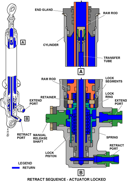
Each actuator has a cylinder, a ram rod, a lock piston, a lock ring and a transfer tube. The actuator also has a manual release shaft which mechanically unlocks the lock piston for maintenance procedures. The manual release shaft gives a visual indication of its position (TEST LOCK or UNLOCK). The cylinder is the body of the actuator which holds internally the ram rod, the lock piston, lock ring and the transfer tube.
The ram rod moves between the cylinder and the transfer tube. It is connected at one end to the pivot door. The other end (the head of the ram rod) has internal lock segments which have a small travel (radially) because of pins in the piston. The lock piston is found before the head of the ram rod and moves between the cylinder and the transfer tube.
The lock piston and the lock ring lock the lock segments (in the stowed position). The transfer tube is attached at one end in the cylinder and the other end has the ram rod which moves along it.

Extend Sequence
Actuator Over-Retracted
The thrust-reverser directional control-unit supplies hydraulic pressure to the retract port of the pivot door actuators. This sends the pressure internally to the retract chamber of the head of the ram rod. Because of this pressure, the head of the ram rod pushes the lock piston and its spring to the unlocked position.

Actuator Extension
When the actuator is over-retracted, the thrust-reverser directional control-unit keeps the pressure on the retract port. Then it also supplies hydraulic pressure to the extend port of the actuator. This sends the pressure (supplied at the extend port) internally to the extend chamber of the head of the ram rod which keeps the lock piston in the unlocked position. The lock segments become free and move in radially.
While the pressure increases in the extend chamber, it becomes more than the pressure in the retract chamber. This change in pressure on the head of the ram rod pushes the ram rod which starts to extend.
While the ram rod extends, the lock segments come in contact with the lock ring. Because the lock segments are made with an angle on their external diameter, this lets the lock ring push the lock segments in radially. The lock segments do not fall in the head of the ram rod because the retainer prevents it. The ram rod is free to move and extend to its fully deployed position.

Retract Sequence
Actuator Retraction
The thrust-reverser directional control-unit removes the hydraulic pressure from the extend port of the actuator. With no pressure in the extend chamber, it changes the pressure on the head of the ram rod which pushes the ram rod to retract. The spring pushes the lock piston to its locked position.
Again, because the lock segments are made with an angle on their external diameter, this lets the lock ring push the lock segments in radially. It lets the lock segments free to move around the lock ring and engage the lock piston. The head of the ram rod contacts and pushes the lock piston and its spring some more to the unlocked position. The ram rod over-retracts which moves the pivot door to the over-retracted position.

Actuator Locked
The thrust-reverser directional control-unit then removes the hydraulic pressure from the retract port of the actuator. With no hydraulic pressure to the actuator, the pressure from the engine exhaust gases pushes the doors back. This extends the ram rod back until the doors engage the S-hooks and lets the spring push the lock piston to the locked position.
Thrust Reverser Hydraulic Primary Lock
The thrust reverser hydraulic primary lock is used to lock the pivot doors. It works together with the thrust reverser electrohydraulic primary lock. Each thrust reverser has one thrust reverser hydraulic primary lock.
The thrust reverser hydraulic primary lock is on the left side of each thrust reverser. It has a valve, piston, and internal check valve to supply safe operation of the primary door lock system.
Hydraulic pressure is supplied to the thrust reverser hydraulic primary lock from the control solenoid valve in the thrust reverser directional control unit. This pressure is supplied to the valve which retracts the piston against the tension of the left S-hook return spring to release the lock. Also, in a sequence, the thrust reverser hydraulic primary lock lets hydraulic pressure go to the thrust reverser electrohydraulic primary lock. The sequence is done by the thrust reverser hydraulic primary lock which stops the pressure internally until its piston is extended and the lock is released.
In turn, the thrust reverser electrohydraulic primary lock extends its piston against the tension of the right S-hook return spring to release the lock. Then, the pivot doors are unlocked. The thrust reverser electrohydraulic primary lock then sends back supply pressure to the direction control valve in the directional control unit.
The thrust reverser hydraulic primary lock is released if the supply pressure is between 464 and 926 psi (3199.16 and 6384.54 kPa). When the supply pressure is removed, the ram rod is retracted by the force of the spring to the locked position.


Thrust Reverser Electrohydraulic Primary Lock
The thrust reverser electrohydraulic primary lock is used to lock the pivot doors. It works together with the thrust reverser hydraulic primary lock. Each thrust reverser has one thrust reverser electrohydraulic primary lock.
The thrust reverser electrohydraulic primary lock is on the right side of each thrust reverser. It has a valve, piston and internal check valve to supply safe operation of the primary door lock system. It also holds a baulk pin solenoid. The solenoid controls a pin that prevents the movement of the piston.
Hydraulic pressure is supplied to the thrust reverser electrohydraulic primary lock in a sequence from the thrust reverser hydraulic primary lock. This pressure is supplied to the valve which retracts the piston against the tension of the right S-hook return spring to release the lock.
Then, the pivot doors are unlocked. The thrust reverser electrohydraulic primary lock then sends back supply pressure to the direction control valve in the directional control unit.
Baulk Pin Solenoid
The baulk pin solenoid is attached to the thrust reverser electrohydraulic primary lock. The solenoid operates from a 28 VDC power source controlled by the FADEC system. When the solenoid is energized, it retracts the pin which lets the piston retract to unlock the pivot door. This configuration keeps the pivot doors locked if the hydraulic system becomes defective.
Throttle Quadrant Assembly
The throttle quadrant assembly (TQA) consists of components mounted in the TQA in the aircraft center pedestal. The primary components of the throttle quadrant assembly include the forward balk solenoid, reverse balk solenoid, and the thrust reverser request switch.

Forward Baulk Solenoid
The forward balk solenoid is connected to the forward balk wall mounted in the throttle assembly.
There are two forward balk solenoids mounted in the TQA, one for the left and one for the right engine.
The forward balk wall prevents forward throttle movement beyond the idle position when it is extended.
The TQA forward balk extends the forward balk wall when it is activated. The forward balk wall returns to the retracted position when the TQA forward balk solenoid is not activated.
Reverse Baulk Solenoid
The reverse balk solenoid is connected to the reverse balk wall mounted in the throttle assembly. There are two reverse balk solenoids mounted in the TQA, one for the left and one for the right engine.
The reverse balk wall prevents reverse throttle movement beyond the reverse idle position until it is retracted.
The TQA reverse balk solenoid retracts the reverse balk wall when it is activated. The reverse balk wall returns to the extended position when the TQA reverse balk solenoid is not activated.
Thrust Reverser Request Switch
The thrust reverser request switch provides contact closure when the throttle is at the reverse idle detent or further back in the throttle movement range. This switch carries current for the thrust reverser activation solenoids and commands to the engine FADEC controller to deploy the thrust reverser.
Thrust Reverser Ground Test Switch
The thrust reverser ground test switch provides an override of the logic that prevents the thrust reverser from deploying when the engine is stopped. It is used for maintenance purposes.
The thrust reverser ground test switch is monitored by the engine FADEC controller and provides fault indications in the event of an open or short type fault within the ground test switch. This type of fault would be annunciated on the maintenance diagnostic computer (MDC).
When a fault within the stow switch is detected, a cyan ENGINE FAULT CAS message annunciates.

01/19/16
Operation
The thrust reversers are stowed and locked during take-off procedures and flight. The thrust reversers are deployed to decrease the speed of the aircraft. They are deployed after aircraft landing (weight-on-wheels) or during the taxiing procedure. The thrust reversers deploy and stow as a result of flight crew operation, aircraft inputs, and electronic control unit (ECU) logic of the FADEC system.
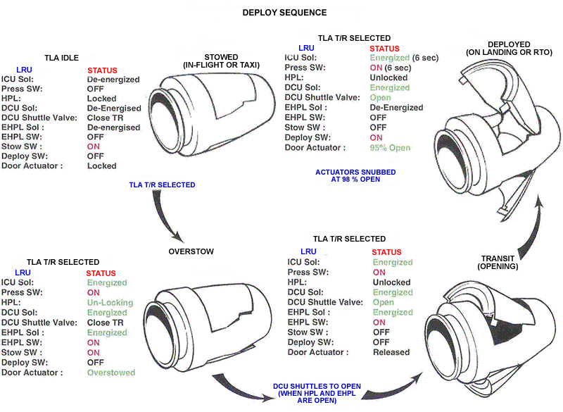
Deploy
There are two stages to deploy the thrust reversers. The sequence starts from the stowed-and-locked position.
There must be a satisfactory configuration for the thrust reversers to deploy. The following conditions are necessary for that configuration:
- Aircraft engines operate
- Thrust reversers stowed and locked
- Main landing gear down and locked
- Aircraft on the ground (weight on wheels)
- Throttle quadrant is set to REVERSE IDLE position
Deploy Stage 1
The throttle quadrant supplies a 28 VDC electrical signal to the ECU, balk pin solenoid, and directional control unit. Also, the ICU receives 28 VDC power from the PSEU.
The logic in the ECU ensures that the configuration is satisfactory for deployment. If the configuration is satisfactory, the ECU supplies a ground to the baulk pin solenoid, thrust reverser directional control unit, and ICU.
The energized balk pin solenoid retracts the pin and lets the piston of the thrust reverser electrohydraulic primary lock move freely. The energized ICU supplies hydraulic pressure to the thrust reverser directional control unit and to the retract port (rod side) of the two pivot door actuators.
The pivot door actuators retract and move the pivot doors to an over-retracted position. With the pivot doors over-retracted, the thrust reverser hydraulic primary lock and thrust reverser electrohydraulic primary lock can be released.
Deploy Stage 2
The energized thrust reverser directional control unit supplies hydraulic pressure to the thrust reverser hydraulic primary lock through a time delay. This time delay gives sufficient time for the pivot doors to over-retract. After the time delay, hydraulic pressure is supplied to the thrust reverser hydraulic primary lock on each thrust reverser. At this point, the direction control valve is internally balanced by the hydraulic pressure from the ICU and its internal spring.
While the thrust reverser hydraulic primary lock retracts, it moves its related S-hook to release the pivot doors. Also, in a sequence, it supplies hydraulic pressure to the thrust reverser electrohydraulic primary lock on each thrust reverser.
While the thrust reverser electrohydraulic primary lock retracts, it moves its related S-hook to release the pivot doors. It also supplies the hydraulic pressure to the head of the direction control valve which causes a condition that is not balanced. The direction control valve then moves to the deploy position.
When the direction control valve moves to the deploy position, it then supplies hydraulic pressure to the extend port (head side) of the pivot door actuators. The pivot door actuators extend and deploy the pivot doors fully. During the deploy travel, hydraulic pressure is supplied to the extend port (head side) of the actuators. There is a loop configuration which decreases the quantity of hydraulic fluid used from each hydraulic system that is necessary to operate the actuators.
Once the pivot doors are fully deployed, the ECU removes the ground from the baulk pin solenoid and the ICU.


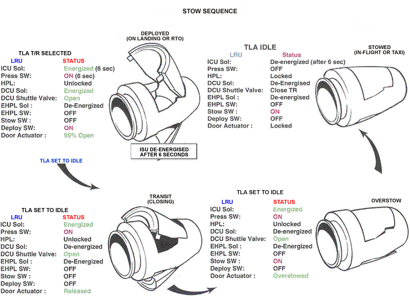
Stow
There are two stages to stow the thrust reversers. The sequence starts from the deployed position.
There must be a satisfactory configuration for the thrust reversers to stow. The following conditions are necessary for that configuration:
- Aircraft engines operate
- Thrust reversers deployed
- Main landing gear down and locked
- Aircraft on the ground (weight on wheels)
- Throttle quadrant set to the forward IDLE position
Stow Stage
The throttle quadrant removes the electrical signal from the baulk pin solenoid and thrust reverser directional control unit.
The logic in the ECU ensures that the configuration is satisfactory to stow the pivot doors. If the configuration is satisfactory, the ECU removes the ground from the thrust reverser directional control unit and supplies a ground to the ICU.
The de-energized thrust reverser directional control unit removes hydraulic pressure from the thrust reverser hydraulic primary lock on each thrust reverser. Also, in a sequence, it removes hydraulic pressure from the thrust reverser electrohydraulic primary lock. The tension of the springs on the S-hooks extends the related piston of the thrust reverser hydraulic primary lock and of the thrust reverser electrohydraulic primary lock.
While the thrust reverser electrohydraulic primary lock retracts, it removes the hydraulic pressure from the head of the direction control valve. The direction control valve is not balanced again and the internal spring causes it to move to the stow position.
When the direction control valve moves to the stow position, it removes hydraulic pressure to the extend port of the pivot door actuators. The retract port of the pivot door actuators stays supplied with hydraulic pressure.
The pivot door actuators over-retract, which stow the pivot doors. During their travel, the pivot doors momentarily push the S-hooks against the tension of their springs. When the pivot doors have over-retracted, the springs automatically move the S-hook back to engage the pivot doors.
De-energized Stage
When the pivot doors are over-retracted, the electrical signal is removed and the ECU also removes the ground from the ICU.
The de-energized ICU removes hydraulic pressure from the thrust reverser directional control unit and the two actuators. With no hydraulic pressure to the pivot door actuators, the pressure from the engine exhaust gases pushes the doors back to engage the S-hooks. The pivot doors are then in the stowed-and-locked position.
The L (R) REVERSER UNSAFE warning message will show when the aircraft is weight on wheels and the thrust reversers are commanded to deploy but in transit.
The L (R) REVERSER FAIL caution message will show when the thrust reversers have mechanically failed.
The L (R) REVERSER INOP status message will show when the inhibit lever is selected to the CLOSE position. This mechanically blocks the isolation valve in the ICU and also prevents its electrical operation.
The EICAS messages that follow are related to the thrust-reverser actuating system:
|
EICAS MESSAGE(S) |
LEVEL (COLOR) |
|---|---|
|
L REVERSER UNSAFE |
WARNING (red) |
|
R REVERSER UNSAFE |
WARNING (red) |
|
L REVERSER FAIL |
CAUTION (amber) |
|
R REVERSER FAIL |
CAUTION (amber) |
|
L REVERSER INOP |
STATUS (white) |
|
R REVERSER INOP |
STATUS (white) |


System Interface
The thrust reverser actuating system interfaces with the following systems/components:
- Proximity Sensor Electronic Unit (PSEU)
- Full-Authority Digital Electronic-Control (FADEC)
- N2 Sensor System
- Control and Feedback System
10/23/20
Component Location Index
| Component Location Index | |||
|---|---|---|---|
| IDENT | DESCRIPTION | LOCATION | IPC REF |
| - | THRUST-REVERSER DIRECTIONAL CONTROL-UNIT (LH) |
PANEL(S) 433CT ZONE(S) 430 |
78-32-01 |
| - | THRUST-REVERSER DIRECTIONAL CONTROL-UNIT (RH) |
PANEL(S) 443CT ZONE(S) 440 |
78-32-01 |
| - | THRUST-REVERSER PIVOT DOORS ACTUATORS (LH) |
PANEL(S) 433CT ZONE(S) 430 |
78-32-02 |
| - | THRUST-REVERSER PIVOT DOORS ACTUATORS (RH) |
PANEL(S) 443CT ZONE(S) 440 |
78-32-02 |
| - | THRUST-REVERSER HYDRAULIC PRIMARY-LOCK (LH) |
PANEL(S) 433CT ZONE(S) 430 |
78-32-05 |
| - | THRUST-REVERSER HYDRAULIC PRIMARY-LOCK (RH) |
PANEL(S) 443CT ZONE(S) 440 |
78-32-05 |
| - | THRUST-REVERSER ELECTRO-HYDRAULIC PRIMARY-LOCK (LH) |
PANEL(S) 433CT ZONE(S) 430 |
78-32-06 |
| - | THRUST-REVERSER ELECTRO-HYDRAULIC PRIMARY-LOCK (RH) |
PANEL(S) 443CT ZONE(S) 440 |
78-32-06 |
| - | THRUST-REVERSER ISOLATION CONTROL-UNIT (LH) |
ZONE(S) 311 | 78-32-07 |
| - | THRUST-REVERSER ISOLATION CONTROL-UNIT (RH) |
ZONE(S) 311 | 78-32-07 |