


Overview
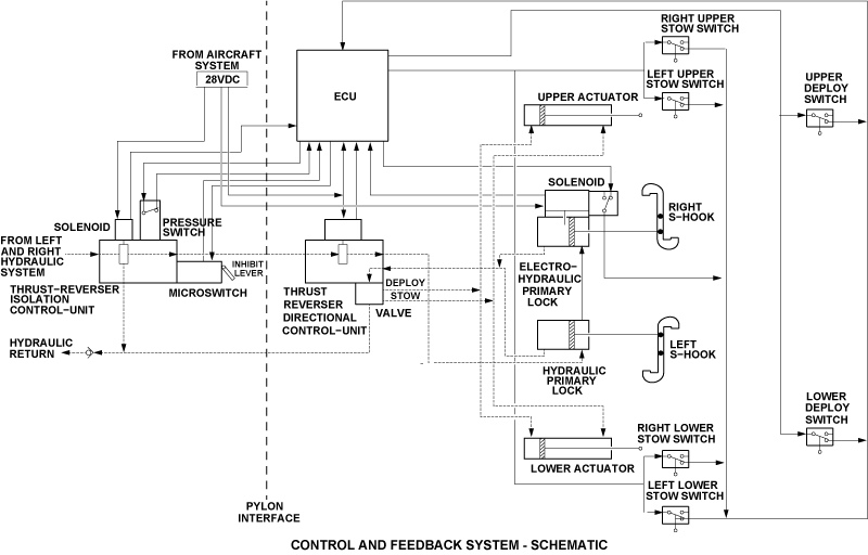
The control and feedback system continuously transmits the position of the thrust reverser pivot doors. It transmits the data about the pivot doors position to the electronic control unit (ECU) of the full authority digital engine control (FADEC) system. The ECU uses the data to control the thrust reverser system and to transmit it to the flight compartment.

Thrust Reverser Door Switches
There are six door switches on each thrust reverser. There are four stow switches and two deploy switches on each thrust reverser. The top pivot door has two upper stow switches and an upper deploy switch. The lower pivot door has two lower stow switches and a lower deploy switch.
The stow switches are on the forward attachment assembly near the front corner of the pivot door. They transmit to the ECU if the pivot door is stowed and if the S-hooks have locked the pivot doors correctly.
The deploy switches are on the side beams. They transmit to the ECU if the pivot doors are fully deployed.


Thrust Reverser Harness
Each thrust reverser has a thrust reverser harness that is made from the following four harnesses:
Stow Switch Harness
The stow switch harness has 16 wires wound together in a fireproof sleeve. The harness has four breakouts, and each breakout has four wires and a connector. The four sections of the stow switch harness are connected to the four stow switches on the pivot doors. The other end of the stow switch harness connects to the multiplexer harness.
The stow switch harness transmits signals to and from the stow switches. The pivot doors operate the stow switches which give an indication to the ECU that the pivot doors are stowed.
Upper Deploy Switch Harness
The upper deploy switch harness has six wires wound together in a fireproof sleeve. The harness has two breakouts. One breakout which has four wires and a connector connects to the upper deploy switch. The other breakout which has two wires and a connector connects to the directional control unit. The other end of the upper deploy switch harness connects to the multiplexer harness.
The upper deploy switch harness transmits signals to and from the upper deploy switch. The pivot door operates the upper deploy switch which gives an indication to the ECU that the upper pivot door is deployed. The electrical signals control the directional control unit.
Lower Deploy Switch Harness
The lower deploy switch harness has 13 wires wound together in a fireproof sleeve. The harness has three breakouts. The first breakout which has four wires and a connector connects to the lower deploy switch. The second breakout which has seven wires and a connector connects to the electrohydraulic primary lock. The last breakout which has two wires and a connector connects to the aircraft systems. The other end of the lower deploy switch harness connects to the multiplexer harness.
The lower deploy switch harness transmits signals to and from the lower deploy switch, the electrohydraulic primary lock and the aircraft systems. The pivot door operates the lower deploy switch which gives an indication to the ECU that the lower pivot door is deployed. The electrical signal controls the electrohydraulic primary lock.
Multiplexer Harness
The multiplexer harness has 19 wires wound together in a fireproof sleeve. The harness has three breakouts. The first breakout which has 16 wires and a connector connects to the stow switch harness. The second breakout which has six wires and a connector connects to the upper deploy switch harness. The last breakout which has 13 wires and a connector connects to the lower deploy switch harness. The other end of the multiplexer harness connects to the ECU.
The multiplexer harness connects the stow switch harness, the upper and the lower deploy switch harnesses to the ECU. It transmits signals to and from the stow switch harness the upper and the lower deploy switch harnesses.


01/19/16
Operation
The thrust reversers can only operate when a weight-on-wheel (WOW) signal (from the PSEU) or a wheel spin up signal (from the brake control unit) is received by the ECU. These signals give the ECU an indication that the aircraft is on the ground. To deploy the thrust reversers, the throttles are set to reverse idle. When the reverse idle is set, power is supplied to the electro-hydraulic primary lock, the directional control unit, the ICU and the ECU. When the ECU receives this input, it calculates other inputs and makes sure that the aircraft configuration is safe to deploy the thrust reversers.
When it is safe to deploy, the ECU supplies a ground to the electro-hydraulic primary lock, the directional control unit and the ICU. This energizes the solenoid of the electro-hydraulic primary lock which retracts the baulk pin to let the valve move freely. The ICU is energized also and it supplies the pressure from the left and right hydraulic system to the directional control unit.
At the same time, the directional control unit is energized. It then connects the received hydraulic pressure to the pivot door actuators, the primary hydraulic lock and the electro-hydraulic primary lock. The actuators and the pivot doors over-retract. The directional control unit supplies hydraulic pressure to the hydraulic primary lock and electro-hydraulic primary lock approximately five seconds after the pivot door actuators. This lets the doors over-retract before the locks are unlocked.
Feedback pressure from the locks move the direction control valve in the directional control unit to the deploy position. This lets hydraulic pressure be supplied to extend the actuators which deploy the pivot doors. When the pivot doors are extended, they operate the deploy switches. The deploy switches send a signal to the ECU which de-energizes the solenoid valve in the ICU and the solenoid in the electro-hydraulic primary lock.
To stow the thrust reverser, the throttles are set to ground idle. When the ground idle is set, the solenoid valve in the ICU is energized. It supplies the pressure from the left and right hydraulic system to the directional control unit again.
At the same time, the directional control unit is de-energized. It then removes the hydraulic pressure from the primary hydraulic lock and the electro-hydraulic primary lock. With no feedback pressure from the locks, the direction control valve in the directional control unit then moves to the stow position. When the directional control valve gets to the stow position, the directional control unit then connects the received hydraulic pressure to the pivot door actuators. Then the actuators and the pivot doors over-retract.
While the pivot doors move to the over-retracted position, they operate the stow switches. The stow swithces send a signal to the ECU which de-energizes the solenoid valve in the ICU. This then removes the hydraulic pressure to the directional control unit and the pivot door actuators.
With no hydraulic pressure to the pivot door actuators, the pressure from the engine exhaust gases pushes the doors back to engage the locks. The reverse thrust annuciation is given on the multi-function display (MFD) in the top left area (engine indication system (EIS) area). The engine indication and crew alerting system (EICAS) (top right of the MFD) gives the crew alerting messages.
The reverse thrust annunciation shows as REV on the MFD. REV shows in red when the TR is in an unsafe condition. It shows in amber when the TR has failed. It shows in white when the TR is in transit. It shows in green when the thrust reverser (TR) is deployed.
The L (R) REVERSER UNSAFE warning message will show when the two stow switches sense a NOT STOWED condition (while the throttle quadrant is set to a forward thrust position). If this occurs, the ECU will automatically decrease the engine to idle and try to stow the pivot doors.
The L (R) REVERSER FAIL caution message will show when the ECU recives signals that the thrust reverser is not safe mechanically. These signals are provided to the ECU by the stow switches, the deploy switches or the aircraft systems. The L (R) REVERSER INOP status message will show when the ECU senses that the microswitch in the ICU is operated (inhibit lever in the CLOSED position).
The EICAS messages that follow are related to the thrust-reverser actuating system:
| EICAS MESSAGE(S) | LEVEL (COLOR) |
|---|---|
| L REVERSER UNSAFE | WARNING (red) |
| R REVERSER UNSAFE | WARNING (red) |
| L REVERSER FAIL | CAUTION (amber) |
| R REVERSER FAIL | CAUTION (amber) |
| L REVERSER INOP | STATUS (white) |
| R REVERSER INOP | STATUS (white) |

System Interface
The control and feedback system interfaces with the following systems/components:
- Left and Right Hydraulic Systems
- Brake Control Unit
- Proximity Sensor Electronic Unit (PSEU)
- Electronic Control Unit
- Thrust Reverser Actuating System
10/23/20
Component Location Index
| Component Location Index | |||
|---|---|---|---|
| IDENT | DESCRIPTION | LOCATION | IPC REF |
| - | LEFT ENGINE THRUST-REVERSER DOOR DEPLOY-SWITCH | PANEL(S) 433CT/CB ZONE(S) 430 |
78-33-01 |
| - | RIGHT ENGINE THRUST-REVERSER DOOR DEPLOY-SWITCH | PANEL(S) 443CT/CB ZONE(S) 440 |
78-33-01 |
| - | LEFT ENGINE THRUST-REVERSER DOOR STOW-SWITCH | PANEL(S) 433CT/CB ZONE(S) 430 |
78-33-01 |
| - | RIGHT ENGINE THRUST-REVERSER DOOR STOW-SWITCH | PANEL(S) 443CT/CB ZONE(S) 440 |
78-33-01 |