


01/21/16
Overview
The distribution system supplies clean, filtered oil at the correct pressure and flow rate to different areas of the engine. The oil decreases the temperature of and lubricates the bearings, the splines, and the seals.
The distribution system supplies oil from the front and rear engine sumps through a filter to the engine bearings and seals, the inner splines and gears, and the accessory gearbox. The oil moves through a fuel heater/oil cooler to remove unwanted heat.
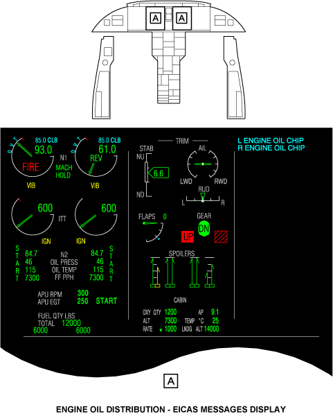
The distribution system gives the flight crew the data to monitor the condition of the chip detector. This data is found on the engine indication system area of the engine indication and crew alerting system (EICAS). The EICAS message display shown gives the related messages for the engine oil distribution system.
The oil in the forward, aft, and accessory gearbox (AGB) sumps lubricates and decreases the temperature of the engine and AGB bearings, splines, and seals. Oil from the forward sump lubricates the bearing supports for the forward end of the high- and low-pressure spool drive shafts. Oil from the aft sump lubricates the bearing supports for the aft end of the high- and low-pressure spool drive shafts. Oil from the AGB sump cools and lubricates the AGB components. The AGB nozzles send a spray of oil on the gears. It is a closed unit with oil retainer seals where necessary. The AGB contains the engine oil tank.


Oil Pump
The oil pump moves oil through the engine and AGB. The AGB turns the pump, which is an easily removed and installed cartridge. The pump is a rotary type with eight elements in four sections. One section moves oil from the oil tank to the engine components (through the oil filter). The three remaining sections move scavenge oil from the forward, aft, and AGB sumps to the oil tank through the chip detector. Each sump has a scavenge screen which catches unwanted material that could harm the pump.

Oil Filter
The oil filter removes contamination from the oil before the oil goes into the engine. The filter has a filter bowl with a 3-micron filter element. The oil filter head has an electrical impending/mechanical bypass valve, pressure relief valve, and pressure adjusting valve.
The bypass valve meters the differential pressure across the filter element. The differential pressure increases as the filter becomes dirty. When the filter becomes blocked, the bypass valve opens to relieve excess pressurized oil from the filter to the oil tank. There is a 500-micron screen which supplies a minimum filter in case the bypass valve opens. A high-pressure condition can occur during engine start when the oil is cold. In this case, the pressure relief valve opens to relieve excess pressure in the oil filter. This prevents damage to the oil system components.
The pressure adjusting valve is a regulator which controls the pressure of the oil from the filter. The valve is set to give the correct oil pressure for the lubrication system.

Electronic Chip Detector
The chip detector is in the top left side of the gearbox adjacent to the oil filter. One bolt holds the sensor casing of the gearbox. There is one electrical connection.
The scavenge oil goes through an electrical chip detector before it goes into the oil storage tank. The chip detector monitors the metal particle contents of the oil to identify a wear problem in the engine. Large particles of unwanted metal material in the oil can indicate unusual wear in the engine. Small particles are caused from usual wear.
The chip detector has internal probe leads. Metal chips in the oil are sensed by the leads in the chip detector. The chip detector supplies a resistance measurement to the ECU. The ECU sends an electrical current burst when the chips are sensed. The ECU records and monitors the electrical current bursts and shows advisory messages on the EICAS.
Each of the three sumps have a magnetic plug and a scavenge screen. The particles contained in these areas can show the source of the unwanted material.

Magnetic Chip Collectors
There are four magnetic chip collectors used to monitor ferrous particles and provide visual indication of distress in the engine oil system. The magnetic chip collectors are mounted on the accessory gearbox. There is a forward sump, aft sump, and two accessory gearbox magnetic chip collectors.
Gearbox Breather Adapter
The gearbox breather adapter lets unwanted fluid pass from the AGB through an air/oil separator to the oil drain mast manifold.

Oil Vent Tubes
The oil vent tubes supply drainage for each part of each engine fire zone and the pylons. The vent tubes are strategically routed from different components and areas of the engine, and are connected to the oil drain mast manifold.
Oil Drain Mast Manifold
The oil drain mast manifold supplies overboard routing of unwanted fluids from the engine. The manifold is found at the 6 o’clock position and is attached to the gearbox breather adapter. It connects to the oil drain mast in the lower cowl. The oil drain mast goes through the nacelle cowl doors when they are closed. The cowl doors include fireproof bulb seals, which compress against the oil drain mast as the doors close.
01/21/16
Operation
The oil pressure pump supplies oil from the oil tank to the filter. The oil then goes to the fuel heater/oil cooler (FHOC) to decrease the oil temperature. The oil goes through a filter screen and then to the supply manifold. The supply manifold distributes the oil to the front, aft, and AGB sumps, which apply the oil directly to the engine and AGB components.
Oil is scavenged from the forward, aft, and AGB sumps by the oil pump. The oil goes through the scavenge screens and the pump to the chip detector, and is returned to the oil tank.
The scavenge oil contains air from the engine secondary air system. The flow of air is necessary to keep the oil in the sumps. The air goes through the tank pressurization valve, which keeps a small positive pressure in the oil tank. The air/oil separator, turned by gears in the AGB, isolates the air from the oil. The unwanted air is then released through the drain mast.
The chip detector has internal probe leads. The resistance between the chip detector probe leads change when metal chips are present. As metal chips increase, it decreases the resistance across the probe leads. The ECU A and ECU B channels measure the resistance.
The chips receive an electrical current burst from the ECU when the resistance is less than 1,000 Ω. The ECU gives five bursts maximum of a 5 A current. The current cleans the metal chips from the oil. If the resistance is more than 10,000 Ω after one or more bursts, the bursts are stopped. If the resistance is less than 5 Ω after one or more bursts, then the bursts are stopped. The metal chips could possibly be bonded to the leads.
When the ECU senses that the same chip remains after five bursts (one after the other), the L (R) ENGINE OIL CHIP advisory message (Table 1) shows on the EICAS. The L(R) ENGINE OIL CHIP advisory message also shows when the ECU has recorded that a total of 20 intermittent bursts have occurred.
The EICAS messages that follow are related to the oil distribution system:
|
EICAS MESSAGE(S) |
LEVEL (COLOR) |
|---|---|
|
L ENGINE OIL CHIP |
ADVISORY (cyan) |
|
R ENGINE OIL CHIP |
ADVISORY (cyan) |

System Interface
The distribution system has interfaces with the system that follows:
- Fuel Distribution System
The oil distribution system has interfaces with the systems that follow:
- Storage
- Oil Indication System
10/22/20
Component Location Index
| Component Location Index | |||
|---|---|---|---|
| IDENT | DESCRIPTION | LOCATION | IPC REF |
| - | OIL PUMP (LH) | ZONE(S) 432BB | 79-21-01 |
| - | OIL PUMP (RH) | ZONE(S) 442BB | 79-21-01 |
| - | OIL FILTER (LH) | ZONE(S) 432BB | 79-21-05 |
| - | OIL FILTER (RH) | ZONE(S) 442BB | 79-21-05 |
| - | CHIP DETECTOR (LH) | ZONE(S) 432BB | 79-21-09 |
| - | CHIP DETECTOR (RH) | ZONE(S) 442BB | 79-21-09 |