01/25/21
Message Overview:
Message Description:
The amber 'TRIM AIR FAIL' caution CAS message indicates a hot air regulating valve has failed, or a cabin / cockpit duct temp sensor is out of range.
- Hot Air Regulating-and-Shut Off Valve failure occurs when the valve remains full closed when commanded open (confirmation time 7s - CBIT and PBIT active). And when the valve remains full open when commanded closed (confirmation time 7 seconds - CBIT and PBIT active)
- When detected, the IASC 2 sends an amber 'TRIM AIR FAIL' message is displayed on the EICAS.
- A failure is detected with the cockpit or cabin duct temp sensor and is out of range, (-55°C or > 300°C).
Possible Causes:
- Hot Air Regulating and Shut-off Valve 1 (HARSOV 1 - Cockpit) (MPE5)
- Hot Air Regulating and Shut-off Valve 2 (HARSOV 2 - Cabin) (MPE6)
- Cabin Duct Temperature Sensor (Cabin DTS) (MT26)
- Cockpit Duct Temperature Sensor (Cockpit DTS) (MT35)
Troubleshooting Tips:
Advisory Wire/Service Bulletin: None
Forum Articles/Infoservice/Newsletter: None
Quick Links:
| Operational Test of the Cabin Pressure Control System | AMM 21-31-00-710-801 |
| Removal of the Integrated Air System (IAS) Controller | AMM 21-31-01-000-801 |
| Installation of the Integrated Air System (IAS) Controller | AMM 21-31-01-400-801 |
| Operational Test of the Integrated Air System (IAS) Controller | AMM 21-31-01-710-801 |
| Removal of the Outflow Valve | AMM 21-31-05-000-801 |
| Installation of the Outflow Valve | AMM 21-31-05-400-801 |
| Wiring - Maintenance Practices - ALL | SPM 20-12-00-02 |
| Wire Repair - Maintenance Practices - ALL | SPM 20-12-10-02 |
Troubleshooting Recommendations:
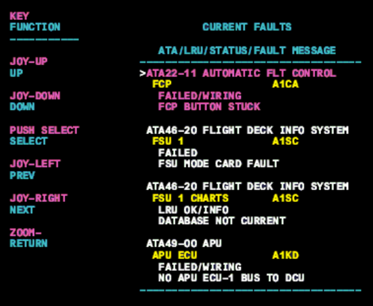
- Interrogate the MDC as follows:
- On the cursor control panel, ensure the toggle switch is to the right and select Anti-Ice, ECS and Fuel buttons simultaneously. The MDC main menu should now be displayed on Display Unit #3.
- Using the joystick, select Current Faults (if the fault is active) or Aircraft History to research stored faults. From Aircraft History you can then select Fault Message History and locate the air condition fault logged.
- Select the MDC fault from the drop down below to provide additional information to assist in troubleshooting.