04/29/24
Message Overview:
Message Description:
The cyan 'ELECTRICAL FAULT' advisory CAS message indicates an electrical system fault has occurred that causes the loss of redundancy in the display of electrical indications.
Possible Causes:
- Electrical System Component(s)
- Associated Wiring
Troubleshooting Tips:
Advisory Wire/Service Bulletin:
- AW300-24-0023 - Nuisance "ELECTRICAL FAULT" CAS Message During APU Start
- AW300-24-0024 - Electrical System - Troubleshooting Tips
- AW300-24-0038 - Nuisance "ELECTRICAL FAULT" CAS Message Upon Engine or APU Shut Down.
- AW300-24-0073 - SB100-24-08 - Modification of DC Power Center (DCPC) - System Reactivation.
- AW300-24-0085 - DC Generator Shaft Spline Wear/Corrosion
- AW300-24-0141 - Electrical System and Flight Display Issues During Flight
- AW300-24-0326 - Generator Control Unit PN R3608-005
Forum Articles/Infoservice/Newsletter: None
NOTE:
- If during engine start a cyan 'ELECTRICAL FAULT' advisory CAS is posted and the MDC shows Fault Code B3-007087, swap the GEN GCUs and monitor if condition follows the GCU.
Quick Links:
| Standard Aircraft Configuration for Maintenance | AMM 12-00-00-867-803 |
| Electrical/Electronic Safety Precautions | AMM 24-00-00-910-801 |
| Electrostatic-Discharge Safety Precautions | AMM 24-00-00-910-802 |
| Removal of the Generator Control Unit (GCU) - Primary | AMM 24-31-13-000-801 |
| Installation of the Generator Control Unit (GCU) - primary | AMM 24-31-13-400-801 |
| Removal of the Generator Power Module | AMM 24-31-21-000-801 |
| Installation of the Generator Power Module | AMM 24-31-21-400-801 |
| General | SPM20-20-00-02-01 |
| Connector Integrity After a Disconnect and Re-Connection | SPM20-20-00-02-06 |
Troubleshooting Recommendations:
- Interrogate the MDC as follows:
- On the cursor control panel, ensure the toggle switch is to the right and select Anti-Ice, ECS and Fuel buttons simultaneously. The MDC main menu should now be displayed on Display Unit #3.
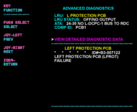
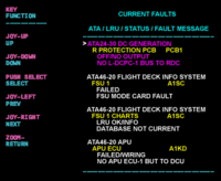
- Using the joystick, select Current Faults (if the fault is active) or Aircraft History to research stored faults. From Aircraft History you can then select Fault Message History and locate the fault. Going into advanced diagnostics will provide an equation ID for the fault identified.
- Select the MDC fault or equation from the drop down below to provide additional information to assist in troubleshooting.