01/25/21
Message Overview:
Message Description:
The amber 'GEAR BAY DET FAIL' caution CAS message indicates the single loop MWW detection element monitored by the FIREX Control Unit has failed, short, open or loss of power.
- If the resistance drops to zero or fall instantly, the CU will report a shorted MWW loop and produce an amber (Caution) 'GEAR BAY DET FAIL' indication.
- The MDC will identify the three options through unique fault equations.
Possible Causes:
- None
Troubleshooting Tips:
Advisory Wire/Service Bulletin:
- AW300-26-0249 - Landing GEAR BAY DET FAIL EICAS Message (20501 - 20999)
Forum Articles/Infoservice/Newsletter: None
Numerous FIREX Control Unit Internal failures (cyan 'FIRE SYS FAULT' advisory CAS message) and Gear Bay detection failures (amber 'GEAR BAY DET FAIL' caution CAS message) are reported on in-service aircraft. The failure remains until the FIREX Control Unit is shutdown or replaced. Once cleared, failure cannot be repeated.
- In all cases the faults were cleared after replacing the FIREX Control Unit. Subsequent bench testing however declared the FIREX Control Units to be NFF and as a result, the root cause of these events remains unknown.
- Kiddie Aerospace suspects that the FIREX Control Unit operational environment may have an influence on the system operation.
Pilot Action: Airspeed....250 KIAS maximum, LANDING GEAR switch....DN, After 5 minutes: LANDING GEAR switch...UP, continue flight.
Quick Links:
| Removal of the FIREX Control Unit | AMM 26-11-01-000-801 |
| Installation of the FIREX Control Unit | AMM 26-11-01-400-801 |
| Electrical Bonding Test | SPM 51-80-00-760-801 |
| Wiring - Maintenance Practices - ALL | SPM 20-12-00-02 |
| Wire Repair - Maintenance Practices - ALL | SPM 20-12-10-02 |
| Electrical Connectors - Maintenance Practice - ALL | SPM 20-20-00-02 |
Troubleshooting Recommendations:
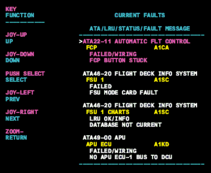
- Interrogate the MDC as follows:
- On the cursor control panel, ensure the toggle switch is to the right and select Anti-Ice, ECS and Fuel buttons simultaneously. The MDC main menu should now be displayed on Display Unit #3.
- Using the joystick, select Current Faults (if the fault is active) or Aircraft History to research stored faults. From Aircraft History you can then select Fault Message History and locate the fault. Going into advanced diagnostics will provide an equation id for the fault identified.
- Select the MDC fault or equation from the drop down below to provide additional information to assist in troubleshooting.