

01/28/21
Message Overview:
Message Description:
The amber 'GEAR DISAGREE' caution CAS message indicates that the gear position and the landing gear switch position do not match.
- The PSEU has detected a discrepancy between gear commanded position and actual position, these indications are caused by the following situations:
- The landing gear does not reach position that agrees with the control handle within maximum swing time-out.
- A landing gear fails to move when commanded (similar to swing time-out, shorter limits).
- Uncommanded movement of a landing gear.
Caution will not be present when fault is detected in an up-lock sensor.
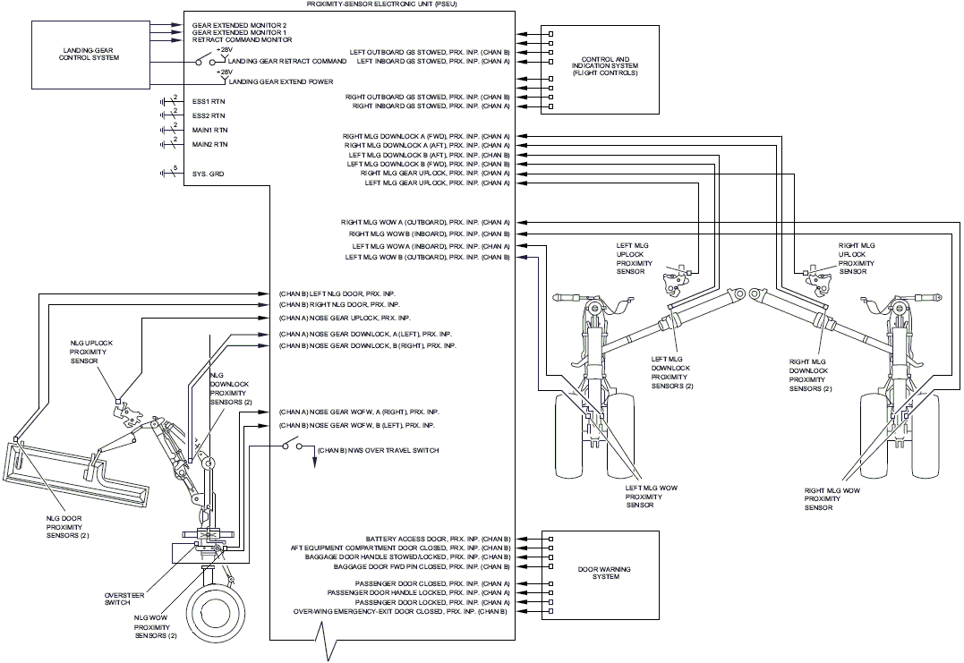
- Gear System Block Diagram
- PSEU non-volatile memory can be downloaded from the MDC for additional trouble shooting information and faults.
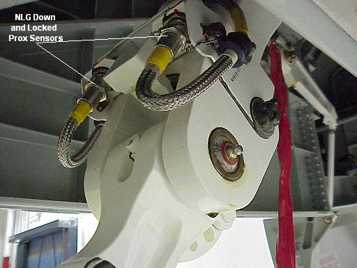
- Advisory Wire 300-32-0084 may provide some relevant information with aircraft that have recently replace the NLG "down & lock" proximity switches PX10 and PX40.
Possible Causes:
- Proximity Sensors
- Proximity Sensor Electronic Unit (PSEU) (A9)
- Associated Wiring
Troubleshooting Tips:
Advisory Wire/Service Bulletin:
- AW300-32-0084 - Nose Landing Gear Downlock Proximity Sensor Installation
- AW300-32-0255 - Data collection for the PSEU Failure
Forum Articles/Infoservice/Newsletter: None
NOTE: If the PROX SYS FAULT (Advisory) CAS message is present at the same time, use SmartFix Plus (SFP) to troubleshoot that message first.
Quick Links:
| Adjustment of the Proximity Sensors | AMM 32-61-00-820-801 |
| Operational Test of the Proximity Sensors | AMM 32-61-00-710-801 |
| Functional Test of the Proximity Sensors | AMM 32-61-00-720-801 |
Troubleshooting Recommendations:
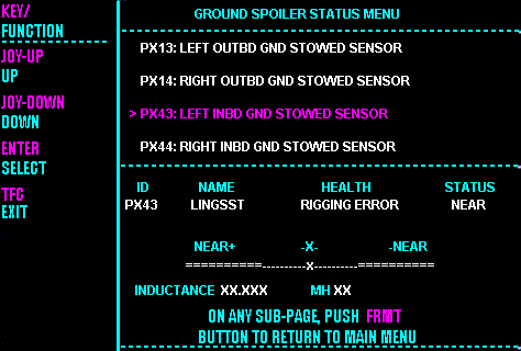
- Use the MDC to view the GEAR SENSOR STATUS MENU as per AMM task 32-61-00-820-801 and adjust any sensor out of tolerance.
- Visually inspect and adjust the proximity sensor switches IAW AMM TASK 32-61-00-820-801, to correct a specific gear disagreement, check and adjust the relevant switches per AMM TASK 32-61-00-710-801, then perform the system functional test of the proximity sensors IAW AMM TASK 32-61-00-720-801.
- The down and lock switches are as follows: NLG (PX10, PX40) Left MLG (PX09, PX39) Right (PX08, PX038).
- The up and lock switches are as follows: NLG (PX06) Left MLG (PX05) Right MLG (PX04).


