

12/10/25
Message Overview:
Message Description:
The cyan 'PROX SYS FAULT' advisory CAS Message indicates a failure in the proximity sensor channel or the loss of the signal from one of the channels.
- There is the possibility of a shorted proximity sensor to its shield that can draw the whole channel down. Verify system wiring integrity, the sensor causing the problem may not be listed as a possible fault in MDC.
- The vendor is working on a improved software version to eliminate most of the nuisance MDC faults the system will produce.
- PSEU status can be directly viewed from the MDC for possible faults.
NOTE: If the cyan 'PROX SYS FAULT' advisory CAS occurs while in flight the crew will also note either the inboard or the outboard ground spoilers did not automatically deploy upon landing. This is a common occurrence when the PSEU faults during flight.
Possible Causes:
- Proximity Sensors
- Proximity Sensor Electronic Unit (PSEU) (A9)
- Associated Wiring
Troubleshooting Tips:
Advisory Wire/Service Bulletin:
- AW300-34-0189 - Pro Line 21 Advanced Avionics Nuisance Messages and FMS-6200 Issues
- AW300-32-0255 - Data collection for the PSEU Failure
Full Throttle Blog/Forum Articles/Infoservice/Newsletter: None
Flight Operation Notifications Manual (FONM): None
NOTES:
- If there is no Global Positioning system (GPS) signal found during this task, you can get an Advisory (cyan) 'PROX SYS FAULT' message and B3 code. If this fault occurs, manually record the date in the FMS CDU to clear the fault message.
- Once the PSEU sensor is identified, cycle or move that system and recheck. It is possible to cycle a system and clear the CAS message.
- If all or any combination of the following CAS are posted at the same time Troubleshoot the PROX SYS Fault (Advisory) first.
PROX SYS FAULT (ADVISORY)
STAB TRIM FAULT (ADVISORY)
SPOILERS FAULT (ADVISORY)
L ENGINE FAULT (ADVISORY)
R ENGINE FAULT (ADVISORY)
Quick Links:
| Standard Aircraft Configuration for Maintenance | AMM 12-00-00-867-803 |
| Electrical/Electronic Safety Precautions | AMM 24-00-00-910-801 |
| Electrostatic-Discharge Safety Precautions | AMM 24-00-00-910-802 |
| Operational Test of the Proximity Sensors | AMM 32-61-00-710-801 |
| Functional Test of the Proximity Sensors | AMM 32-61-00-720-801 |
| Adjustment of the Proximity Sensors | AMM 32-61-00-820-801 |
| Removal of the Proximity-Sensor Electronic Unit (PSEU) | AMM 32-61-09-000-801 |
| Installation of the Proximity-Sensor Electronic Unit (PSEU) | AMM 32-61-09-400-801 |
Troubleshooting Recommendations:
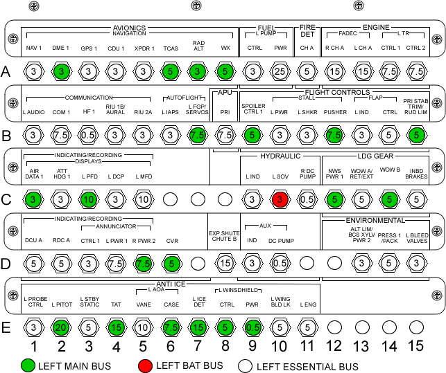
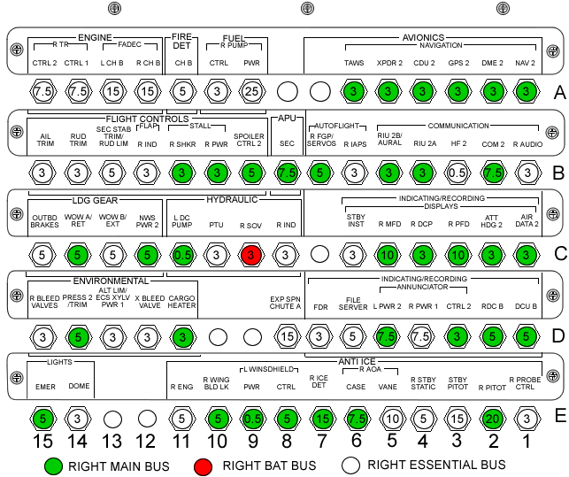
- DO NOT pull and reset the WOW A and WOW B circuit breakers (CB1-C13, CB1-C14, CB2-C13, CB2-C14)
- Use the MDC to view the GEAR SENSOR STATUS MENU as per AMM task 32-61-00-820-801 and adjust any sensor out of tolerance.
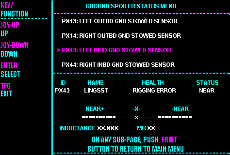
- Interrogate the MDC as follows:
- On the cursor control panel, ensure the toggle switch is to the right and select Anti-Ice, ECS and Fuel buttons simultaneously. The MDC main menu should now be displayed on Display Unit #3.
- Using the joystick, select Current Faults (if the fault is active) or Aircraft History to research stored faults. From Aircraft History you can then select Fault Message History and locate the fault. Going into advanced diagnostics will provide an equation id for the fault identified.
- Select the MDC fault or equation from the drop down below to provide additional information to assist in troubleshooting.


