

07/28/25
Message Overview:
Message Description:
The amber 'R REVERSER FAIL' caution CAS message indicates a failure in the thrust reverser system that prevents continued operation.
- The respective thrust reverser has failed.
Possible Causes:
- Hydraulic Quantity Indicator
- Electro-Hydraulic Primary-Lock (EHPL)
- Thrust Reverser (TR) Lower Deploy Switch
- Thrust Reverser (TR) Upper Deploy Switch
- Thrust Reverser (TR) Lower Door (Lower Door)
- Thrust Reverser (TR) Upper Door (Upper Door)
- Thrust Reverser (TR) Lower Pivot Door Actuator (PDA)
- Thrust Reverser (TR) Upper Pivot Door Actuator (PDA)
- Thrust Reverser Multiplexer (TR MUX) Connectors
- Thrust Reverser (TR) Isolation Control-Unit (ICU) Wiring Harness
- Thrust Reverser (TR) Isolation Control-Unit (ICU)
- Thrust Reverser (TR) Isolation Control-Unit (ICU) Inhibit Indication Switch
- Electronic Control Unit (ECU) A
- Electronic Control Unit (ECU) B
- Thrust Reverser (TR) doors failed to move from the stow position
- Throttle Quadrant Assembly (TQA) Solenoid Wiring
- Throttle Quadrant Assembly (TQA) Solenoids
- TR Deploy Command Signals
- Associated Wiring
Troubleshooting Tips:
Advisory Wire/Service Bulletin:
- SIL AS907-6 - AS907 FAILED THRUST REVERSER STOWING
Full Throttle Blog/Forum Articles/Infoservice/Newsletter: None
Flight Operation Notifications Manual (FONM): None
NOTES:
- Check Lower TR Deploy Switch and Bracket for possible wear. Refer to Honeywell SIL AS907-6.
- You may need to inspect the FADEC's and Multiplexer's connectors for proper installation, contamination or damage. Check the system after the connectors have been reinstalled properly.
Quick Links:
| Standard Aircraft Configuration for Maintenance | AMM 12-00-00-867-803 |
| Electrical/Electronic Safety Precautions | AMM 24-00-00-910-801 |
| Electrostatic-Discharge Safety Precautions | AMM 24-00-00-910-802 |
| Connect Electrical Power to the Aircraft | AMM 24-00-00-861-801 |
| Component Location | AMM 78-30-00-992-801 |
| Thrust-Reverser Safety Precautions | AMM 78-30-00-910-801 |
| Removal of the Thrust Reverser | AMM 78-30-00-000-801 |
| Installation of the Thrust Reverser | AMM 78-30-00-400-801 |
| Removal of the Thrust-Reverser Access Panels | AMM 78-30-00-000-802 |
| Installation of the Thrust-Reverser Access Panels | AMM 78-30-00-400-802 |
| Deactivation of the Thrust Reverser (For Maintenance) | AMM 78-30-00-040-801 |
| Activation of the Thrust Reverser (For Maintenance) | AMM 78-30-00-440-801 |
| Deactivation of the Thrust Reverser | AMM 78-30-00-040-802 |
| Activation of the Thrust Reverser | AMM 78-30-00-440-802 |
| Operational Test of the Thrust Reverser | AMM 78-30-00-710-801 |
| General Visual Inspection of the Left/Right Thrust Reverser (Thrust Reverser Deployed) | AMM 78-30-00-210-801 |
| General Visual Inspection of the Thrust Reverser | AMM 78-30-00-210-802 |
| Detailed Inspection of the Thrust Reverser Firewall | AMM 78-30-00-220-801 |
| Detailed Inspection of the Thrust Reverser Seals | AMM 78-30-00-220-802 |
Troubleshooting Recommendations:
- Make sure the following Circuit breakers are set to IN:
Left Thrust Reverser
L TR Ctrl 1 - CB1 A14
L TR Ctrl 2 - CB1 A15
Left FADEC (ECU)
L CH A - CB1 A13
L CH B - CB2 A13
Right Thrust Reverser
R TR Ctrl 1 - CB2 A14
R TR Ctrl 2 - CB2 A15
Right FADEC (ECU)
R CH A - CB1 A12
R CH B - CB2 A12 - Interrogate the MDC as follows:
- On the cursor control panel, ensure the toggle switch is to the right and select Anti-Ice, ECS and Fuel buttons simultaneously. The MDC main menu should now be displayed on Display Unit #3.
- Using the joystick, select Current Faults (if the fault is active) or Aircraft History to research stored faults. From Aircraft History you can then select Fault Message History and locate the fault. Going into advanced diagnostics will provide an equation id for the fault identified.
- Select the MDC fault or equation from the drop down below to provide additional information to assist in troubleshooting.
- Use Honeywell E-Engines web site for system troubleshooting, link provided above.


The table has a list of possible system failures that can post the message:
| UNSAFE or FAIL or ENGINE FAULT | A failure of the brake unit or weight on wheel mismatch, this is a channel comparison and there is a mis-compare. |  |
| UNSAFE or FAIL or ENGINE FAULT | Single channel operation of the thrust reverser due to a cross channel connection problem. FADEC reports a connection fault. |
 |
| UNSAFE or FAIL or ENGINE FAULT | The throttle position disagrees with the thrust reverser position. FADEC reports a throttle position fault. |
 |
| UNSAFE or FAIL | Doors Fail to Deploy fully, EICAS indication appears during deployment. FADEC reports lower or upper door no deploy. |
 |
| UNSAFE or FAIL | Doors Fail to Stow fully, EICAS indication appears during closing. FADEC reports lower or upper door no stow. |
 |
| UNSAFE or FAIL | Upper or lower door fails to Stow or deploy, EICAS indication appears during deployment. FADEC reports lower or upper door actuation fault. |
 |
| UNSAFE or FAIL | Upper or lower door fails move during deployment, EICAS indication appears during deployment. FADEC reports lower or upper door no movement. |
 |
| UNSAFE or FAIL | Upper or lower door fails move during stow, EICAS indication appears during closing. FADEC reports lower or upper door no movement. |
 |
| UNSAFE or FAIL | Upper or lower door fails move during stow or deployment, EICAS indication appears during opening or closing. FADEC reports no thrust reverser movement. |
 |
| UNSAFE or FAIL or ENGINE FAULT | The ICU pressure switch has faulted and the EHPL Balk switch has faulted. FADEC reports ICU pressure switch circuit failure. |
 |
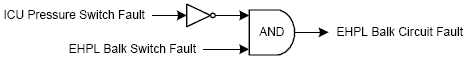
| UNSAFE or FAIL or ENGINE FAULT | The ICU pressure switch has faulted and the EHPL Balk switch has faulted. FADEC reports EHPL balk circuit failed. |
 |
| UNSAFE or FAIL or ENGINE FAULT | The ICU pressure switch and the EHPL Balk switch have failed. FADEC reports a hydraulic pressure control fault. |
 |
| UNSAFE or FAIL or ENGINE FAULT | ICU pressure switch and EHPL balk circuit has failed. FADEC reports multiple hydraulic circuit failures. |
 |
| UNSAFE or FAIL or ENGINE FAULT | Switch verification is good, however thrust reversers have timed out and a possible balk solenoid, or ICU pressure loss has occurred. FADEC reports no hydraulic pressure to thrust reverser. |
 |