

09/04/19
Leak Detection Elements (LDE) Troubleshooting:
LDE Insulation Resistance Verification
To troubleshoot LDE insulation integrity, measure the insulation resistance between the center conductor and its outer sheath.
There are two ways to measure the insulation between the LDE inner conductor and outer sheath. The method to be used will be determined by the type of test equipment used.
- LCR meter method - measure the insulation resistance using an approved LCR Meter (ref: Illustrated Tools and Equipment Manual). The LCR meter must be adjusted to a test frequency of 1 kHz and 1 VAC (ref: user manual). The LDE measurement is performed using the 'R' function of the LCR meter. 'R' is the symbol for resistance in Ohms.
- TEGAM meter method - measure the conductance using a TEGAM meter (ref: Illustrated Tools and Equipment Manual). With the TEGAM meter, the test frequency and voltage is preset. Therefore no specific adjustment is required. The LDE measurement is performed using the 'G' function. If the reading is fluctuating, use the average value as a measurement result. 'G' is the symbol for conductance in Siemens.
CAUTION: It is not permitted to use a Megger (Mega-ohmmeter) to verify LDE (loops). Permanent damage can occur to the loops.
CAUTION: Using a multimeter measuring from outer sheath to center conductor will also cause damage to the LDE.
To perform insulation check of the LDE, connect the test meter between center conductor and outer sheath as shown in Fig 1.
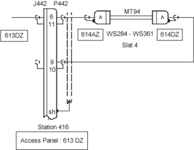
The insulation check can be performed from a connector. If we use MT94 (in Fig 2) as an example, we can connect the meter at P442 and measure between pin 6 and 11. This is possible because pin 11 is connected to MT94 outer sheath via the shield and pin 6 is connected to pin A of MT94. Refer to the applicable Troubleshooting instruction sheet for the expected values.
Siemens & Ohms
The relationship between Siemens & Ohms when measuring conductance is as follows:
Resistance (ohms) = 1 / conductance (siemens)
Fig 1. Insulation Check Setup
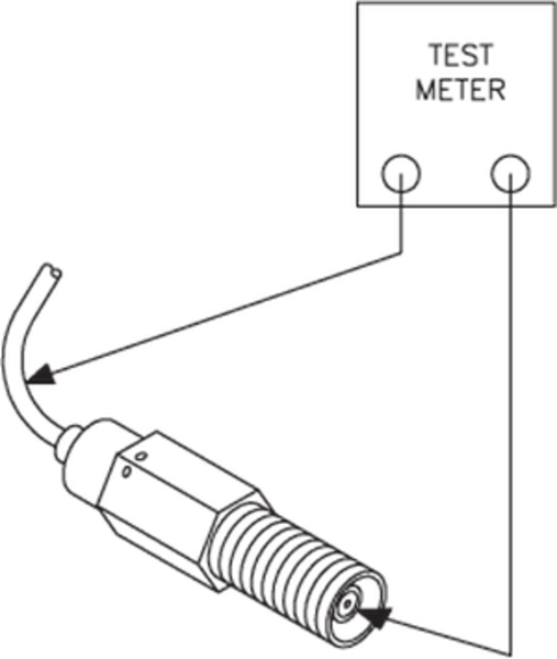
Fig 2. Sample Loop Schematics
LDE Linear Resistance Check:
To perform a linear resistance check of a leak detection element, use any approved meter in resistance 'R' mode (ohms). Connect the test meter to measure the linear resistance as shown in Fig 3.
To measure the linear resistance of MT94 (in Fig 2) as an example, connect the test meter to P442 between pin 6 and 9.
Refer to the applicable Troubleshooting instruction sheet for the expected values.
Fig 3. Resistance Test Setup

Troubleshooting Procedure For Bleed Loop Short Circuit:
- If the CAS message is still present, perform a RUN EVENT LOC TEST of the IASC via the MDC.
- If a Short circuit is indicated on one of the loops, note the location of it in terms of total length percentage with IASC or in terms of F.S. or W.S.
- Once the Shorted element has been identified, disconnect it and measure the characteristics of the element with TEGAM 252 instrument and compare it with the nominal values provided in the Bleed loop CMM.
- If it is not good, replace the element.
- If the element resistance and isolation are correct, measure the isolation between each of the element connector center connector and its outer shell. The resistance should be OPEN. If not, replace the connector.
Troubleshooting for OPEN Circuit:
- Disconnect P4 of the IASC #1 or #2 (Depends on where the loop is connected).
- With an analog multimeter, check resistance of the respective pins. If there is higher resistance than described per the table below then locate the connector that is disconnected and fix the connection.
- If all connectors are OK, check for discontinuity within each element and replace the element.
LOOP VALUE (OHMS) LH and RH Bleed 75.0 LH and RH Pylon 14.0 LH and RH Fuse Wing 136.0 LH and RH Pylon Wing 136.0 Pack 15.4 Trim 62.0
Troubleshooting Tips:
If a failure condition is present only with Bleed Air or Wing Anti-Ice applied, then the affected system can be operated on the ground without restriction for troubleshooting purposes. This is possible on the Wing Anti-Ice system in the aircraft, because the wing temperature is auto regulated by the system and is therefore protects the structure from any possible overheat condition.
When a failure condition is temperature related, operate the system on the ground and try to duplicate the condition(s).