

07/31/25
Message Overview:
Message Description:
Abnormal yaw activity is observed in flight.
Possible Causes:
- Loose Exterior Panel Or Fairing
- Engine Sync
- Autopilot
- Rudder Trim
- Rudder System Mechanical Component
Troubleshooting Tips:
Advisory Wire/Service Bulletin:
- AW300-22-0372 - Autopilot Troubleshooting Data
Full Throttle Blog/Forum Articles/Infoservice/Newsletter: None
Flight Operation Notifications Manual (FONM): None
Quick Links:
| Standard Aircraft Configuration for Maintenance | AMM 12-00-00-867-803 |
| Operational Test of the Yaw Damper Linear-Actuator (For Return to Service) | AMM 22-22-01-710-801 |
| Operational Test of the Yaw Damper Linear-Actuator | AMM 22-22-01-710-803 |
| Electrical/Electronic Safety Precautions | AMM 24-00-00-910-801 |
| Electrostatic-Discharge Safety Precautions | AMM 24-00-00-910-802 |
| Connect Electrical Power to the Aircraft | AMM 24-00-00-861-801 |
| Functional Test of the Rudder Control System | AMM 27-21-00-720-801 |
| Functional Test of the Rudder Cable Tension | AMM 27-21-00-720-802 |
| Functional Test of the Rudder Backlash | AMM 27-21-00-720-803 |
| Detailed Inspection of the Rudder Power Control Unit (PCU) Centering Spring | AMM 27-21-00-220-805 |
| Operational Test of the Input/Output Concentrator Unit (IOC) | AMM 31-45-05-710-801 |
| Operational Test of the Inertial Reference System (IRS) | AMM 34-45-00-710-801 |
Troubleshooting Recommendations:
Ground Tests:
- Inspect the exterior of the aircraft for loose panels or fairings.
- Make sure aircraft meets the requirement of the AMM task 27-21-00-720-802 (Functional Test of the Rudder Cable tension).
- Perform the detailed inspection of the Rudder Power Control Unit (PCU) centering spring: AMM 27-21-00-220-805.
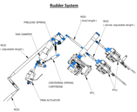
- Perform the detailed inspection of the highlighted sections in blue below (bearings & rod ends). Move rods and linkages and check for loose parts or excessive play (backlash). Inspect the preload spring and the centering spring cartridge.
- Perform the Functional test of the Rudder PCU for internal leakage and record values (AMM 27-21-05-720-801) (This test is used to verify the PCU's flutter suppression capacity and performance).
- Perform the Functional test of the Rudder backlash and record values (AMM 27-21-00-720-803).
- Perform the Functional test of the Rudder control system and record values (AMM 27-21-00-720-801)
NOTE: Do not disconnect the top and bottom rudder PCU. Disregard steps 4, 5, 6of the PROCEDURE section. - For the next step, ensure the FDR is powered and ready to record the DATA.
- Perform the Operational Test of the Inertial Reference System (IRS) (AMM 34-45-00-710-801).
- Perform the Operational Test of the Input/Output Concentrator Unit (IOC) (AMM 31-45-05-710-801).
- Perform the Operational Test of the Yaw Damper Linear-Actuator (For Return to Service) (AMM 22-22-01-710-801).
- Perform the Operational Test of the Yaw Damper Linear-Actuator (AMM 22-22-01-710-803).

Subsequent Flight Tests:
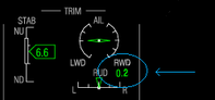
- Pull up the STALL TEST PAGE on the PILOT MFD as follows: On CCP, push A/ICE, ECS and HYD buttons simultaneously. This displays the flight control degrees of deflection (position) In addition, the rudder trim indication should appear next to the rudder trim synoptic.
- At 15000 ft, 200 kts:
- Manually fly the aircraft (AP OFF and YD OFF)
- Set the engine AUTO SYNC switch to N1 and verify engine power is matched.
- Stabilize the aircraft. Adjust the rudder trim to center the L/R EFIS inclinometers. Verify that both slip/skid indicators match.
- Record rudder trim position from the MFD (next to the rudder trim synoptic).
Rudder trim position:_____________ - From the stall test page, record the rudder control surface position.
Rudder control surface position:_____________
NOTE: If possible, take a picture or quick video of the cockpit parameters.
- Record rudder trim position from the MFD (next to the rudder trim synoptic).

If the Yaw activity occurs, perform the following checks:
- Push the FDR EVENT button and record the following information:
- Date:_____________
- Aircraft time:_____________
- Altitude:_____________
- Airspeed:_____________
- YAW RATE from the stall test page:_____________
- Flight Condition (climb, level flight, etc...):_____________
- Engine N1%:_____________
- Set the Engine AUTO SYNC switch to N2. Take note if this helps reducing the yaw motion.
- Return the AUTO SYNC switch to N1.
- Change engine thrust to try to isolate each engine.Note if this changes behavior.
- Record the rudder trim position:_____________
- Monitor the rudder control surfaces movement from the stall test page. (Take some notes or if possible, take a short video of the cockpit parameters).
- Add some Rudder trim input to see if this helps reducing the yaw motion.
- If the Yaw activity is still felt, disengage the Auto Pilot system and monitor if the Yaw motion stops. Record the rudder control surfaces movement from the stall test page. (If possible, take a short video of the cockpit parameters).
- NOTE: Perform the following step ONLY if the flight crew is comfortable with the proposed instructions.
Disengage the YAW damper. (YD OFF) and monitor if the Yaw motion stops. Record the rudder control surface's movement (Rate) from the stall test page. (If possible, take a short video of the cockpit parameters).
Post flight procedure:
- Send the FDR download to the Bombardier Customer Response Center (CRC) for evaluation.
- Send the MDC download to the CRC for evaluation.
- Provide all notes, picture and videos taken during flight.
- Provide any additional detail the flight crew or maintenance personnel may have on the issue.
- Do close out.