04/26/21
Message Overview:
Message Description:
The amber 'HDG' caution flag identifies that the IRS heading is split or the IRSs can not cross compare to each other.
- Inaccurate heading information can be caused by a flux valve, flux valve wiring failure, or magnetic field disruption around the flux valve.
- The IRS calibration may need to be re-accomplished, or the IRS unit may be drifting. Checking the aircraft on a compass rose or know heading (aircraft runway lineup) to determine the inaccurate side assists trouble shooting.
- Cross comparator problems could be associated with a bad IOC, IRS Computer or Data bus failure.
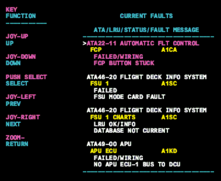
MDC troubleshooting information may help isolate data validity, prior to component replacement and data bus ring-out.

Possible Causes:
- Flux Valve
- Magnetic Field Disruption around the Flux Valve.
- Inertial Reference System (IRS) Calibration
- Input/Output Concentrator (IOC) (A4-IOC)
- Inertial Reference Unit 1 (IRS 1) (A233)
- Inertial Reference Unit 2 (IRS 2) (A232)
- Data Bus Failure
- Associated Wiring
Troubleshooting Tips:
Advisory Wire/Service Bulletin: None
Forum Articles/Infoservice/Newsletter: None
Quick Links:
| Removal of the Input/Output Concentrator Unit (IOC) | AMM 31-45-05-000-801 |
| Installation of the Input/Output Concentrator Unit (IOC) | AMM 31-45-05-400-801 |
| Operational Test of the Input/Output Concentrator Unit (IOC) | AMM 31-45-05-710-801 |
| Operational Test of the Inertial Reference System (IRS) | AMM 34-45-00-710-801 |
| Removal of the Inertial Reference Unit (IRU) | AMM 34-45-01-000-801 |
| Installation of the Inertial Reference Unit (IRU) | AMM 34-45-01-400-801 |
| Wiring - Maintenance Practices - ALL | SPM 20-12-00-02 |
| Wire Repair - Maintenance Practices - ALL | SPM 20-12-10-02 |
Troubleshooting Recommendations:
The IRS system is susceptible to splits (Compass headings disagree by more than 5°) in or around hangars or on the tarmac where underground plumbing or electrical wiring runs. Taxi the aircraft away from these areas, select the "slew" switch to either L or R with the system still in slave, this will "quick align" the IRS system to the flux valve input.
- If the system does not match up, check the area around the flux valves for magnetic hardware.
- If no magnetic hardware is found around the flux valves, the system will require a compass swing, perform the compass swing IAW AMM TASK 34-21-00-820-802.