


Overview
The terrain-avoidance warning system (TAWS) helps to prevent accidents caused by controlled flight-into-terrain (CFIT) or dangerous windshear conditions. If the aircraft moves out of specified limits (alert boundaries) of alert envelopes, the TAWS gives related aural alert messages, visual annunciations, and displays. The TAWS uses hardware, software, and functional integration with other systems and flight compartment controls/instruments.
The TAWS is a line replaceable unit (LRU) that supplies all the functions of the standard ground-proximity warning system (GPWS) and also other additional functions that give added protection. The TAWS supplies three different functions that operate independently. These functions are:
- Ground proximity warning
- Windshear detection and alerting
- Terrain/obstacle awareness alerting and display
The ground proximity warning function gives reactive warnings (warnings for which something must be done because of real time input to the TAWS). The warnings help prevent controlled flight-into-terrain (CFIT). The warnings are put into categories of five modes (GPWS modes 1 through 5).
Each mode has an aural alert and a related visual annunciation. The GPWS can also supply an additional mode (mode 6), which can include altitude related callouts and/or an excessive bank angle callout. The displays give the GND PROX and PULL UP GPWS annunciations on the primary flight displays (PFD).
The windshear detection and alerting function (also identified as mode 7) gives windshear caution or warning alerts if inertial accelerations against air mass accelerations (along the flight path and perpendicular to the flight path) are more than specified threshold values. The TAWS gives the WINDSHEAR annunciations on the PFD.
The TAWS installation gets data from sufficient aircraft sensors so that the TAWS gives windshear alerts (cautions/warnings).
The terrain/obstacle awareness alerting and display function gives warnings for the area in front of the aircraft flight path (based on the aircraft present position supplied by the global positioning system (GPS) and the TAWS projection of the aircraft flight path (based on current aircraft conditions).
The TAWS contains a worldwide data base that includes terrain, airports, and other data. The TAWS compares its flight path projection with the data base to find dangerous conditions in front of the aircraft. The TAWS gives aural and visual warnings to tell the pilot if it finds a dangerous condition.
The TAWS also can show a graphical representation of elevation properties on the flight compartment displays. The TAWS gives the GND PROX and PULL UP terrain/obstacle annunciations on the PFD. The TAWS also shows a graphical representation of the terrain elevation on the PFD or multi-function display (MFD).
04/28/25
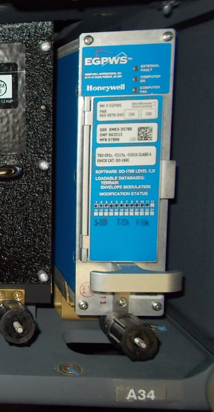
Terrain Avoidance Warning System Computer
The TAWS computer is a solid state processor and the primary system component. The computer is installed in the RH equipment rack, at FS344.18.
The TAWS computer operates from the 28 VDC R MAIN bus through circuit breaker CB2-A6 (TAWS), on the right circuit-breaker panel (CBP2).
The TAWS gives visual and aural warnings and alerts related to a dangerous flight path, aircraft configuration, or windshear condition. It also contains continuous self-test functions and automatically transmits fail condition data to the engine indication and crew alerting system (EICAS) displays and/or MFDs.
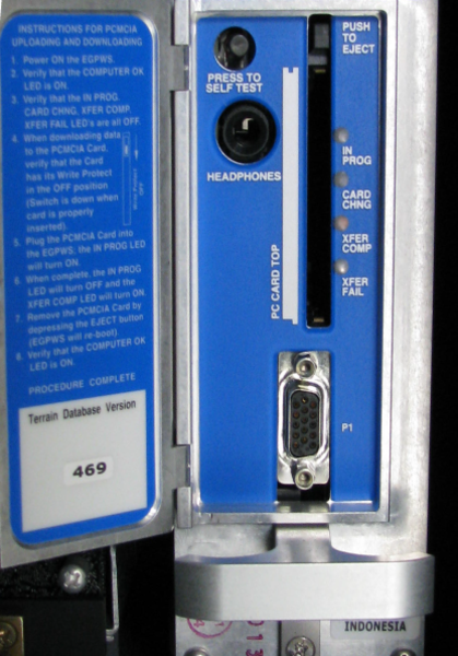
The computer has a port in the front for connecting a personal computer modular interface adapter (PCMIA) card, a RS 232 port to interface with a portable computer, a test switch to start a self-test and LEDs to indicate system status.
The TAWS computer supplies two types of functions:
- TAWS alerts functions
- TAWS interface functions
The TAWS alert functions are the primary functions of the terrain-avoidance warning system. The TAWS alert functions include the three independent functions that follow:
- The basic ground-proximity warning system (GPWS) functions and their related options
- The two enhancement functions:
- Windshear detection and alerting function
- Terrain/obstacle awareness alerts and warnings function with the related display options
The basic GPWS functions operate independently of the two enhancement functions.
For example, if the terrain/obstacle awareness display function has a fail condition, it will have no effect on the operation of the GPWS function (if the input signals necessary for GPWS operation are available).
The Runway Overrun Awareness and Alerting System (ROAAS) (ATA 34-36-00) function is hosted by the TAWS computer.
The TAWS interface functions are secondary functions that process the TAWS input/output signals, and supply the TAWS operation status to the operator.
The TAWS interface functions include:
- Input signal processing (includes filtering and signal monitoring)
- Alert output processing (includes alert prioritization, voice message synthesis, audio output and display and warning lamp drivers)
- Built-in test and monitoring (includes flight-compartment-activated self-test)
- Interface for uploading software and databases (uses a smart cable/PCMCIA card). This is a capability of the system available to the user
- Front panel maintenance test connector for system test and troubleshooting
- System status light-emitting-diodes (LEDs) on the LRU front panel to show EXTERNAL FAULT, COMPUTER OK and COMPUTER FAIL conditions.
Selection of the different options related to the TAWS alert and interface functions is made with pin strapping.


TAWS Computer Tray
The TAWS computer tray is installed in the RH equipment rack. It is used to correctly install the TAWS computer in the equipment rack and to prevent excessive vibrations of the computer during the flight. It also helps the crew do the maintenance procedure quickly and satisfactorily, if and when necessary.
12/06/18
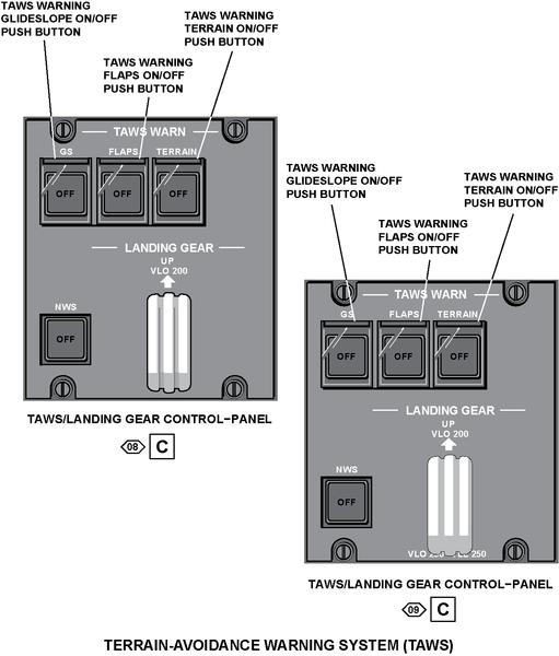
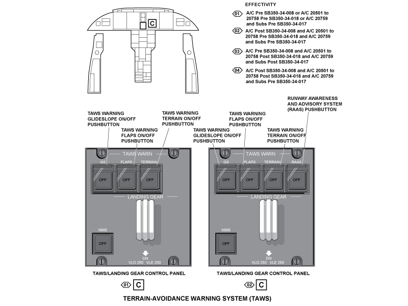
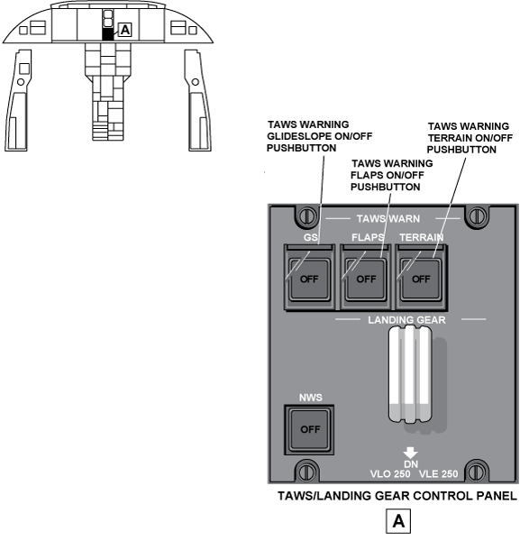
TAWS/Landing Gear Control Panel
The TAWS/Landing Gear control panel is located on the main instrument panel in the flight Compartment.
The panel contains guarded switch/lights (pushbuttons). The switches have the following labels:
- GS
- FLAPS
- TERRAIN
- RAAS (Option) (On A/C Post SB 350-34-008)
- SAL (Option) (On A/C 20501 to 20758 Post SB 350-34-018 and A/C 20759 and Subs Post SB 350-34-017)
TAWS WARN GS
The TAWS WARN GS switch is used to cancel mode 5 below glideslope alerts (below 2,000 ft (609.60 m) AGL). When the switch is pushed, the light in the background of the switch comes on and the OFF is seen. Also, the GLIDESLOPE aural and visual alerts are stopped. When not pushed, the TAWS operates as usual.
TAWS WARN FLAPS
The TAWS WARN FLAPS switch is used to cancel the TOO LOW FLAPS or TERRAIN aural and visual warnings during specified conditions. When the switch is pushed, the light in the background of the switch comes on and the OFF is seen. Also, the TOO LOW FLAPS or TERRAIN aural and visual alerts are stopped. When not pushed, the TAWS operates as usual.
TAWS WARN TERRAIN
The TAWS WARN TERRAIN switch is used to cancel the enhanced functions (terrain/obstacle awareness alert and display and terrain clearance floor) of the TAWS during specified conditions.
When the switch is pushed, the light in the white background of the switch comes on and the black OFF letters are seen.
Also, the enhanced functions of the TAWS are cancelled, but modes 1 through 7 operate as usual. When not pushed, the enhanced functions of the TAWS operate as usual.
On A/C Post SB 350-34-008, the TAWS RAAS switch is used to turn off the smart runway/smart (SR/SL) landing feature.
On A/C 20501 to 20758 Post SB 350-34-018 and A/C 20759 and Subs Post SB 350-34-017, the TAWS SAL switch is used to turn on the steep approach landing (SAL) feature.
The TAWS/LANDING GEAR control-panel has also two controls that are used for the landing-gear control system:
- LANDING GEAR control handle, used to control the landing gear extension and retraction
- NWS pushbutton annunciator (PBA), used to arm or disarm the nose-wheel steering system
RAAS (Post SB350-34-008)
The TAWS RAAS switch is used to turn off the smart runway/smart (SR/SL) landing feature.
04/21/16
Operation
- Modes
- Mode 1 Excessive Descent Rate
- Mode 2 Excessive Terrain Closure Rate
- Mode 3 Altitude Loss After Takeoff
- Mode 4 Unsafe Terrain Clearance
- Mode 5 Excessive Glideslope Deviation
- Mode 6 Altitude Awareness/Excessive Bank Angle Callouts
- Mode Enhancement - Envelope Modulation
- Mode 7 Windshear Detection and Alerting
- Terrain/Obstacle Awareness Alerting and Display Function
- RAAS (Runway Awareness and Advisory System) (Post SB350-34-008)
The terrain-avoidance warning system supplies the flight crew with:
- All the functions that are usually supplied by a standard GPWS (GPWS functions)
- Additional functions that enhance the standard GPWS (Enhancement functions)
The GPWS functions monitor and supply warnings related to the flight parameters/conditions that follow:
- Excessive descent rate (mode 1)
- Excessive terrain closure rate (mode 2)
- Altitude loss after takeoff (mode 3)
- Unsafe terrain clearance (mode 4)
- Excessive glideslope deviation (mode 5)
- Altitude awareness/excessive bank angle callouts (mode 6)
The GPWS modes include an audio declutter function that starts the voice alert once, then not again unless the situation has degraded by 20%. This function applies to modes 1, 3, 4, and 5. Also, the GPWS modes can include the options that follow:
- Geometric altitude source (envelope modulation)
- Terrain clearance floor (TCF) and runway field clearance floor (RFCF) option
The enhancement functions are added to the GPWS functions to supply:
- Windshear detection and alerting (identified as mode 7)
- Terrain and obstacle awareness alerts and warnings with optional display functions
With the GPWS functions (mode 1 through 6 and the related options) and the enhancement functions, the TAWS supplies the flight crew with aural messages, visual annunciations, and terrain/obstacle graphical displays.
These TAWS outputs are supplied to the flight crew through:
- The different modes of operation and options that are set in the TAWS installation
- The terrain/obstacle awareness alerting and display function
- The TAWS aural-message-priority function
Modes Of Operation
The TAWS operation is adapted to each aircraft through a selection of the different possible options. Selection of the TAWS options is made with TAWS computer pin strapping.
Mode 1 Excessive Descent Rate
Mode 1 gives alerts when the aircraft has excessive descent rate near the terrain. It is in operation for all parts of flight and is independent of the aircraft configuration. Mode 1 has two limits for the barometric sink rate (feet per minute (FPM)) of the aircraft descent as related to the aircraft radio altitude. The alert boundaries are a function of the aircraft vertical speed (barometric altitude rate) and radio altitude. If the aircraft moves through the outer alert boundary, the aural message SINKRATE is given. The computer gives aeronautical radio incorporated (ARINC) 429 bits as output to show visual annunciations (GND PROX) on the PFD. If the aircraft moves through the inner alert boundary, the aural message PULL UP is given as well as the visual annunciation PULL UP, on the PFD.

Mode 2 Excessive Terrain Closure Rate
Mode 2 gives alerts when the aircraft moves in the direction of the terrain at too high a rate. It is not necessary for the aircraft to be in a descent to cause a mode 2 alert. Level flight (or a climb) in the direction of terrain can cause a dangerous terrain closure rate.
The TAWS computer mixes radio altitude and vertical speed in a non-linear complementary filter to calculate the terrain closure rate variable. Mode 2 has two sub-modes, mode 2A and mode 2B. As shown by the mode 2 illustrations, mode 2A and mode 2B have different alert envelopes. Selection of one of these sub-modes is related to the TAWS options installed. The aircraft configuration controls which sub-mode is set for the aircraft.
Movement through the mode 2A alert envelope starts the TERRAIN TERRAIN aural message and starts the GND PROX annunciation on the PFD. If movement continues, the PULL UP aural message is given continuously until the aircraft moves out of the warning envelope and thus starts an altitude gain function. If the terrain clearance continues to decrease, the visual alerts continue until the aircraft gains 300 ft (91.44 m) of barometric altitude, 45 seconds have elapsed, or the altimeter loses track. At that point in time, all visual indications cancel.
The top alert boundary of the mode 2A alert envelope changes as a function of aircraft speed. As airspeed increases from 220 kts to 310 kts, the alert boundary expands to give increased alert times at higher airspeeds. The boundary decreases when the protection of the terrain/obstacle awareness function is available and of high precision.
Mode 2B gives a desensitized alert envelope that makes possible a normal landing approach. This alert envelope also makes it possible to move near to the terrain without unwanted alerts. Mode 2B is in operation for the first 60 seconds after takeoff or when flaps are set to the landing position. Mode 2B is also in operation when the aircraft is within ±2 dots of the glideslope centerline.
Movement through the mode 2B envelope with gear or flaps not in landing configuration starts the TERRAIN TERRAIN aural message and shows the GND PROX annunciation on the PFD. If movement continues, the PULL UP aural message is given continuously and the PULL UP annunciation on the PFD is shown. The indications continue until the aircraft moves out of the warning envelope.
If the aircraft moves through the mode 2B envelope with gear and flaps in landing configuration, the TERRAIN aural message is given continuously. It is given until the aircraft moves out of the warning envelope. Whenever possible, envelope modulation is used to eliminate unwanted, system-induced warnings.

Mode 3 Altitude Loss After Takeoff
Mode 3 gives alerts when the aircraft altitude decreases too much immediately after takeoff or during a missed approach. The altitude loss variable is related to the change of altitude at mean sea level (MSL) from the start of the unwanted descent. The amount of the decreased altitude (permitted before an alert is given) is a function of the height of the aircraft above the terrain.
Mode 3 operates between 10 to 1,500 ft (3.05 to 457.20 m) radio altitude. Mode 3 is in operation after takeoff or go-around, when landing gear or flaps are not in landing configuration. It stays in operation until the TAWS finds that the aircraft has increased in altitude so that it is no longer in the takeoff phase of flight. Movement through the mode 3 boundary starts the DON'T SINK aural message and shows the GND PROX annunciation on the PFD. The visual annunciations stay on the display until there is a positive rate of climb.

Mode 4 Unsafe Terrain Clearance
Mode 4 gives alerts when there is not sufficient terrain clearance in relation to phase of flight and speed. Mode 4 has three forms: 4A, 4B and 4C.
Mode 4A is in operation during cruise and approach with gear not in landing configuration (gear up). The standard boundary for mode 4A is 500 ft (152.40 m) radio altitude. Movement through the standard boundary with the gear still up starts the TOO LOW GEAR aural message. Above 190 kts, the boundary increases linearly with airspeed to a maximum of 1,000 ft (304.80 m) radio altitude at 250 kts or more.
Movement through this boundary starts a TOO LOW TERRAIN message and shows the GND PROX annunciation on the PFD.
Mode 4B is also in operation during cruise and approach, but with gear in landing configuration (gear down). When the landing gear is lowered, mode 4B is in operation and the boundary decreases to 245 ft (74.68 m). Movement through the boundary below 159 kts and with gear and flaps not set for landing starts the TOO LOW FLAPS aural message and shows the GND PROX annunciation on the PFD. Movement through the boundary above 159 kts starts the TOO LOW TERRAIN aural message and shows the GND PROX annunciation on the PFD.
Mode 4C is in operation during the takeoff with gear or flaps not set in landing configuration (at takeoff). Mode 4C is related to a minimum terrain clearance (floor) that increases with radio altitude during takeoff. A value equal to 75% of the current radio altitude is collected in a long-term filter. A decrease of radio altitude below the filter value with gear or flaps up starts the TOO LOW TERRAIN aural message and shows the GND PROX annunciation on the PFD.
Optional variations to the mode 4 alert boundaries are available through envelope modulation. When terrain awareness is enabled, the mode 4 A/B TOO LOW TERRAIN voice is limited to values below the TOO LOW FLAPS voice.
Mode 4 can be enhanced with a terrain clearance floor (TCF) alert function.
The TCF operates during takeoff, cruise, and final approach to adds another level of protection to the standard GPWS functions. It makes an increased terrain clearance envelope around the destination runway that is directly related to the distance from the runway.
TCF alerts are related to current aircraft location, radio altitude and a distance related to the nearest runway center point position minus half the runway length. TCF completes mode 4 protection. It gives an alert when there is not sufficient terrain clearance even when in landing configuration.
The TCF function is further enhanced with the addition of a runway field clearance floor (RFCF) alert function. The RFCF function is based on current aircraft location, nearest runway center point, and height (above sea level (ASL), not AGL) above the destination runway.
Movement through the TCF or RFCF envelope starts the TOO LOW TERRAIN aural message and shows the GND PROX annunciation on the PFD. This aural message occurs once when the initial envelope penetration occurs, and once thereafter for each 20% degradation in radio altitude (AGL) or altitude (ASL).

Mode 5 Excessive Glideslope Deviation
Mode 5 gives two levels of alerts when the aircraft flight path becomes lower than the glideslope beam on front course instrument-landing-system (ILS) approaches.
The first alert starts when the aircraft is more than 1.3 dots below the beam and starts the GLIDESLOPE aural message and shows the GND PROX annunciation on the PFD. This is called a soft glideslope alert because the volume level of the GLIDESLOPE alert is approximately one half (-6 dB) that of the other alerts.
The second alert boundary occurs below 300 ft (91.44 m) radio altitude with greater than 2 dots deviation. It is called a loud or hard glideslope alert because the volume level is greater than the other GPWS alerts. The aural and visual messages of mode 5, cancel when the TAWS WARN/GS OFF pushbutton, on the TAWS/LANDING GEAR control-panel, is pushed when the aircraft is below 2,000 ft (609.60 m) radio altitude.

Mode 6 Altitude Awareness/Excessive Bank Angle Callouts
Mode 6 gives a menu of radio altitude callouts from which selections can be made during landing approach. It also gives an optional alert for excessive bank angle.
Mode 6 gives audio callouts for descent below established altitudes and minimums, and alerts for excessive bank angle. Excessive bank angle starts the BANK ANGLE aural message twice and then stops it unless the roll angle increases by an additional 20%.
Specific callouts are set (by TAWS computer pin strapping) with configuration items from predefined menus. Mode 6 callouts give aural output indications, but do not give visual indications. A smart five-hundred-foot callout is available. It is given when the TAWS finds that a non-precision approach is done, or that the aircraft is outside ±2 dots glideslope deviation.
A MINIMUMS-MINIMUMS callout is given when the aircraft descends through the MIN ALTITUDE (RA or BARO). The decision height (DH) callout function operates between 1,000 ft and 10 ft (304.80 m and 3.05 m) above ground level (AGL). The minimum descent altitude (MDA) callout function starts when the corrected altitude is 200 ft (60.96 m) more than the MDA. The landing gear must be down to start these callouts.
The volume level of the mode 6 callouts is set through TAWS computer pin strapping.
There are no visual annunciations for mode 6.

Mode Enhancement - Envelope Modulation
The envelope modulation function gives better alert protection at some key locations throughout the world, while it makes nuisance margins better at others. This is made possible with the use of navigational signals from GPS.
Before it is accepted for envelope modulation, the data is cross-examined with ground based navigational aids, altimeter and heading data, and stored terrain characteristics. Modes 4, 5, and 6 are expanded at some locations to give alert protection consistent with normal approaches. Modes 1, 2, and 4 are desensitized at other locations to prevent nuisance warnings which are the result of unusual terrain or approach procedures.
In all cases, very specific data is used to correlate the aircraft position and phase of flight before modulation of the envelopes. The tables which keep the envelope modulation data are kept in nonvolatile memory.
Mode 7 Windshear Detection and Alerting
The TAWS gives the windshear detection and annunciation functions. During takeoff or final approach, mode 7 gives alerts for flight into an excessive windshear condition.
The windshear caution (or pre-alert) gives a WINDSHEAR annunciation on the PFD and optional aural output indications.
The windshear warning gives the WINDSHEAR annunciation on the PFD and siren WINDSHEAR WINDSHEAR WINDSHEAR aural message.
Windshear detection is in operation between 10 and 1,500 ft (3.03 and 457.20 m) AGL during the initial takeoff and final approach. Alerts are given when the level of windshear is more than established threshold values. The actual windshear value measured is the vector sum of inertial against air mass accelerations along the flight path and perpendicular to the flight path. These shears are the result of vertical winds and horizontal winds that change rapidly.
The figure, typical microburst encounter, shows the windshear microburst phenomenon and related windshear caution and warning levels. Windshear warning alerts are given for decreased head wind (or increased tail wind) and dangerous vertical down drafts. Windshear caution alerts are given for increased head wind (or decreased tail wind) and dangerous up drafts.

Terrain/Obstacle Awareness Alerting and Display Function
- Terrain Awareness Alerting
- Obstacle Awareness Alerting
- Terrain Awareness Display
- TAWS Aural-Message-Priority Function
An important property of the TAWS is the terrain and obstacle awareness alert and display function.
This function uses aircraft geographic position, aircraft altitude, and a terrain and obstacle data base to predict possible conflicts between the aircraft flight path and the terrain. This function also gives graphic displays of the terrain or obstacle.
The TAWS contains a worldwide terrain data base of runway, terrain, and obstacle data. The data base gives the necessary data for navigation between regions without loss of terrain awareness coverage.


Terrain Awareness Alerting Function
The terrain awareness alert algorithms continuously calculate terrain clearance envelopes in front of the aircraft. The TAWS gives alerts if the boundaries of these envelopes are in a conflict with terrain elevation data in the terrain data base. Two envelopes are calculated. One envelope is related to a terrain caution-alert level and the other to a terrain warning-alert level. The algorithms are designed to meet the criteria that follow:
- Operational compatibility—Minimal unwanted alerts during normal flight operations and approach procedures
- Improved terrain awareness warning times—Give sufficient alert times for all flight phases and conditions
- Robustness—Tolerant of aircraft position, altitude signal, and database errors
The caution and warning envelopes use the TCF as a baseline, and look ahead distance of the aircraft as a function of airspeed and flight path angle. The figure, terrain caution and warning envelope boundaries, gives the boundaries for the basic terrain caution envelope (or yellow alert envelope) and terrain warning envelope (or red alert envelope).
Movement through the caution envelope boundary starts the CAUTION TERRAIN, CAUTION TERRAIN aural message and shows the GND PROX PFD annunciation. Some installations can possibly use the TERRAIN AHEAD aural message. At the same time, terrain areas that are in conflict with the caution specifications are shown in solid yellow color on the terrain display. This is described in the terrain-awareness display-function section.
Movement through the warning envelope boundary starts the TERRAIN TERRAIN, PULL UP aural message and shows the PULL UP annunciation on the PFD. Some installations can possibly use the TERRAIN AHEAD, PULL UP aural message. At the same time, terrain areas that are in conflict with the warning specifications are shown in solid red color on the terrain display. This is described in the terrain-awareness display function section.
Obstacle Awareness Alerting Function
The TAWS can find and gives obstacle alerts for obstacles contained in the TAWS obstacles data base. The data base contains the known man-made obstacles that are higher than 100 ft (30.48 m) AGL.
Obstacle data is not available for all regions of the world. It is not possible to make sure that all obstacles for a given region are included in the data base. The current obstacle data base is obtained from the United States National Oceanic and Atmospheric Administration (NOAA). It includes obstacles in the United States and parts of Canada, Mexico and the Bahamas.
The terrain awareness alert function processes the obstacle data in the same way as terrain. The same visual annunciations that are in operation for terrain caution/warning alerts are in operation for obstacle caution/warning alerts.
The obstacle voice is almost the same as the terrain alert, but for an obstacle alert, the word OBSTACLE replaces the word TERRAIN. The obstacle alert function is set by TAWS computer pin strapping.
Movement through the caution envelope boundary starts the CAUTION OBSTACLE, CAUTION OBSTACLE aural message and shows the GND PROX annunciation on the PFD. Some installations can possibly use the OBSTACLE AHEAD aural message. At the same time, obstacle areas which are in conflict with the caution criteria are shown in solid yellow color on the terrain display. This is described in the terrain-awareness display-function section.
Movement through the warning envelope boundary starts the OBSTACLE OBSTACLE, PULL UP aural message and activates the PULL UP annunciation on the PFD. Some installations can possibly use the OBSTACLE AHEAD aural message. At the same time, obstacle areas which are in conflict with the warning criteria are shown in solid red color on the terrain display. This is described in the terrain-awareness display-function section.
Terrain Awareness Display Function
The TAWS shows a display of terrain data in weather radar format per ARINC-708/708A (ARINC 453). When the terrain display is shown, it replaces the weather radar display on the PFD and/or MFD. The terrain display can be made available to the flight crew at all time. When the conditions for a terrain caution or a terrain warning are found, the TAWS supplies a pop-up output (to MFD only). This can be used to alternate the flight compartment displays between the weather radar and the terrain display. The EFIS shows terrain on the PFD and MFD.
Areas of terrain that satisfy the terrain caution-alert criteria are shown in solid yellow, and areas of terrain that satisfy the terrain warning-alert criteria are shown in solid red. Terrain that is significantly close to the aircraft, but satisfies neither the caution or warning criteria, is shown as a green, yellow or red dot pattern. The perceived brightness is less than that of the yellow caution or red warning area. The density of the pattern is coarsely changed to show terrain altitude in relation to the aircraft. If the optional peaks mode (description of this mode will follow) is set, the display of terrain in relation to absolute terrain elevation is also given.
There are two possible background-terrain awareness display modes:
- The standard mode
- The peaks mode (optional)
For both modes the background display is calculated from the aircraft altitude related to the terrain data.
In the standard mode operation, only terrain that is at 2,000 ft or less below the aircraft, is graphically shown on the PFD/MFD. Terrain is shown in colors and shading patterns in relation to the vertical displacement between the terrain elevation and the current aircraft altitude. The terrain indications in the standard mode are as follows:
- Terrain more than 2,000 ft (609.60 m) below the aircraft is not shown. And, the terrain display is usually blank during the en route portion of the flight
- High and low density green display patterns show terrain that is below the aircraft and at 2,000 ft (609.60 m) or less from the aircraft altitude
- Red and yellow dot patterns give an indication of terrain near or above the current altitude of the aircraft
- Solid yellow and red colors give an indication of caution and warning areas in relation to the flight path of the aircraft
The peaks mode option is set by TAWS computer pin strapping. The optional peaks mode adds density patterns and level thresholds to the standard mode display patterns and levels. These added levels are from absolute terrain elevations relative to the range and distribution of terrain in the display area. The peaks display is thus a combined display applicable to all phases of flight. At altitudes safely above all terrain for the set display range, the terrain is shown independently of aircraft altitude.
To give situational awareness, the highest and lowest elevations are emphasized. This increased awareness can be particularly valuable in the event of an unplanned descent, off-route deviation, or to get a view of terrain before descent.
The peaks mode gives terrain indications as follows:
- A solid green level shows the highest non-threatening terrain
- The standard lower density green display pattern shows middle and upper terrain in the display area. It also show terrain that is in an area of 2,000 ft (609.60 m) around the aircraft
- The red and yellow dot patterns are not changed and continue to show terrain that is near or above the current altitude of the aircraft
- Solid yellow and red colors are also not changed and continue to show caution and warning areas relative to the flight path of the aircraft
- Terrain identified as water (0 ft (0 m) MSL) can optionally be shown as cyan dots
The peaks mode display is such that higher level colors and densities override lower color and densities. This function gives maximum situational awareness of the most significant terrain relative to the altitude and flight path of the aircraft.
With the peaks mode, two elevation numbers, which identify the highest and lowest terrain currently on the display, are shown in a separate display area (PEAKS indications). The two elevation numbers show terrain in hundreds of ft (30.48 m units) above MSL. The terrain elevation numbers are shown as follows:
- The highest terrain number is shown on top with the lowest terrain number below it
- The highest terrain number has the same color as the highest terrain color pattern on the display
- The lowest terrain number has the same color as the lowest terrain color pattern on the display
- Only one elevation is shown when the display is all black or cyan. This occurs when the aircraft is over water or almost flat terrain with no appreciable difference in terrain elevations

TAWS Aural Message Priority Function
Because some of the flight conditions (for which the TAWS gives messages) are more dangerous than others, the TAWS aural messages are given different levels of importance.
Thus, an aural message given for more dangerous condition will override and cancel a less important message.
The table that follows shows the alert prioritization scheme in descending order of importance (the most important message is at the top of the list).

RAAS (Runway Awareness and Advisory System) (Post SB 350-34-008 )
The RAAS offers improved situational awareness for the flight crew in order to help lower the probability of runway incursion incidents and accidents by providing timely aural messages to the flight crew during ground taxi, takeoff (including rejected takeoffs), final approach, and landing/roll-out operations. Existing EGPWS protection and operation is unaltered by the addition of RAAS.
Advisories/cautions are generated based upon the current aircraft position when compared to the location of the airport runways, which are stored within the Honeywell EGPWS Runway Database.
The aurals can be grouped into two categories:
- Routine Advisories (annunciations the flight crew will hear during routine operations), and
- Non-Routine Advisories/Cautions (annunciations the flight crew will seldom or perhaps never hear).
RAAS provides the flight crew with five 'routine' advisories. Three of these annunciations will be heard by the crew in normal operations, providing increased position awareness relative to the runway during taxi and flight operations. They are intended to reduce the risk of a runway incursion. The two remaining 'routine' advisories provide information about the aircraft location along the runway, and are intended to reduce the risk of overruns. These advisories are:
- Approaching Runway - In Air advisory provides the crew with awareness of which runway the aircraft is lined up with on approach.
- Approaching Runway - On-Ground advisory provides the flight crew with awareness of a proximate runway edge being approached by the aircraft during taxi operations.
- On Runway advisory provides the crew with awareness of which runway the aircraft is lined-up with.
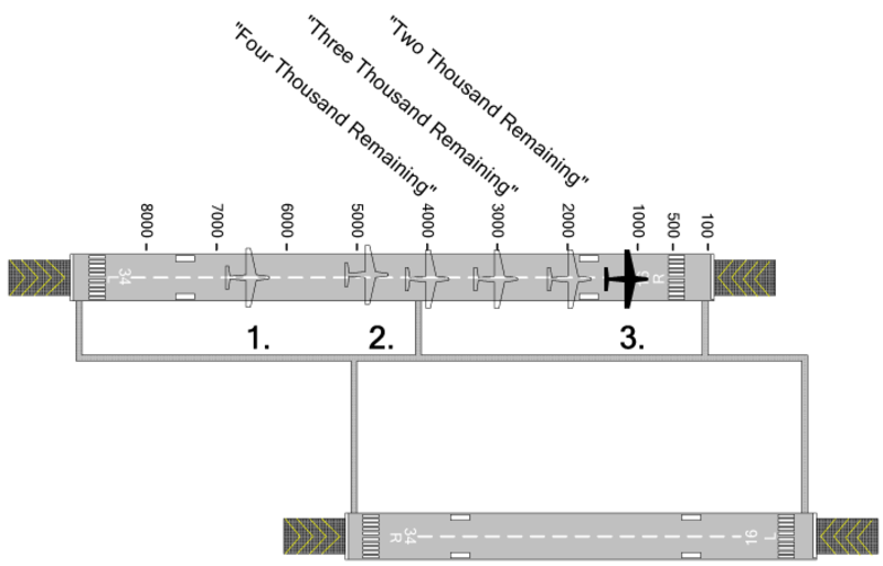
- Distance Remaining advisories enhance crew awareness of aircraft along-track position relative to the runway end.
- Runway End advisory is intended to improve flight crew awareness of the position of the aircraft relative to the runway end during low visibility conditions.
In addition, RAAS provides the flight crew with several 'non-routine' advisories/cautions. These annunciations are designed to enhance safety and situational awareness in specific situations not routinely encountered during normal aircraft operations. Some of the RAAS advisories include distance information. The unit of measure used for distance can be configured to be either meters or feet.
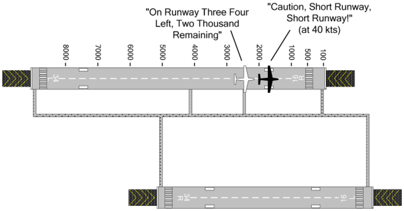
- Approaching Short Runway - In-Air advisory provides the crew with awareness of which runway the aircraft is lined-up with, and that the runway length available may be marginal for normal landing operations. If desired, an additional caution annunciation can be enabled which provides the crew with awareness that the issue has not been resolved when the aircraft is on final approach.

- Insufficient Runway Length - On-Ground Advisory provides the crew with awareness of which runway the aircraft is lined-up with, and that the runway length available for takeoff is less than the defined minimum takeoff runway length. If desired, an additional caution annunciation can be enabled which provides the crew with awareness that the issue has not been resolved when the aircraft is on the final stage of takeoff.
- Extended Holding on Runway advisory provides crew awareness of an extended holding period on the runway.
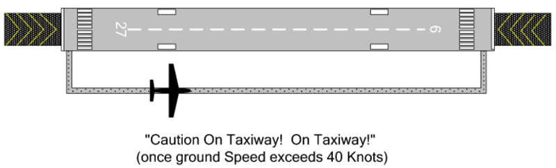
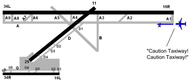
- Taxiway Take-Off advisory enhances crew awareness of excessive taxi speeds or an inadvertent take-off on a taxiway. If desired, this function can provide a caution annunciation in lieu of an advisory annunciation.
- Distance Remaining advisories provides the flight crew with position awareness during a Rejected Take-Off (RTO).
- Taxiway Landing alert provides the crew with awareness that the aircraft is not lined up with a runway at low altitudes.
Each RAAS function is independently enabled using the RCD. When enabled, the RAAS functions operate automatically, without any action required from the flight crew.
In addition to the aural annunciations provided, visual annunciations can be activated in the form of caution indications if the annunciation is considered a caution condition. Visual text annunciations can also be configured to be overlaid on the terrain display for a period of time when the condition is entered. RAAS inoperative status will be indicated during the EGPWS Self Test if RAAS is enabled via the RCD and the status indicates the function is inoperative. RAAS status will be displayed on the Terrain Display. This is active only when the aircraft is on the ground. Depending on the status, the message may be shown immediately, or it may require a change in the displayed range (to a higher or lower range) in order to be viewable. Inhibition of the RAAS function via cockpit selection may be configured.
The SR/SL is configurable for voice gender (male/female), unit of measurement (feet/meters), and visual displays can be configured to on and off. The configurable items are done at installation only by program pin strapping.
Controls and Displays
When set, the PFDs and MFDs display graphical terrain data on compatible formats. TAWS alerts are shown on the PFD when commands are given by the TAWS computer.
TAWS mode, fault annunciations, and EICAS messages are shown on the PFD and/or MFD, when applicable.

TAWS PFD Controls
TR/WX Pushbutton
When the TR/WX pushbutton, on the DCP, is pushed to set the display of terrain, the format automatically changes to be compatible, if necessary. If terrain is shown and an incompatible format is set, the terrain overlay is automatically removed.
Regardless of the current format (when terrain is not the active overlay and the TAWS gives a terrain awareness warning or caution), if the TR/WX pushbutton is pushed, it causes an immediate response.
The first momentary push of TR/WX will set terrain to show on the display at its default 10 NM range and PPOS (present position) format.
Regardless of the current format, if the TR/WX is pushed for more than 1 second, it will automatically set terrain for display at its default 10 NM range and PPOS format.
Terrain Overlay
Terrain data and weather radar reflectivity cannot be shown at the same time on a single display. Manual or automatic selection of terrain data automatically cancels weather radar (WX) and lightning (LX), if installed. Selection of WX or WX/LX automatically cancels terrain. Terrain is shown on compatible formats when set for display and terrain data is valid. Terrain display is removed when not set for display or a terrain fault annunciation is shown.
Terrain Range
Range can be set from the same-side display control panel (DCP) RANGE button. Terrain data is available with set ranges up to 300 NM. If the display range is at a value of more than 300 NM when the pilot sets terrain, the display range will automatically decrease to 300 NM. If configuration strapping unit (CSU) strapping word 9 bit 14 is set, then the 600 NM range is enabled. If terrain data selection has been set for display, selection of display ranges of more than 300 NM is not permitted. Range stays at its current selection if terrain is not set.

TAWS MFD Controls
Except the differences given below, the MFD controls for TAWS are the same as those given for the PFD.
TR/WX Pushbutton
The display of terrain on the MFD is set with the TR/WX pushbutton, on the cursor control panel.
Conditional Terrain Pop-Up
Conditional TAWS pop-up is the automatic selection of terrain on all MFDs which have pop-up enabled when a terrain/obstacle warning or caution occurs while terrain is not shown on the same side PFD.
The MFD format is automatically changed to PPOS and the normal range is changed to 10 NM. If a format which is not compatible with terrain is shown, then TR selection is made or a TAWS pop-up occurs and pop-up is enabled. PPOS with terrain overlay is shown.
If set with CSU strapping, graphical terrain data is automatically shown on the MFD when a terrain hazard is found. This function is called conditional terrain pop-up. The terrain pop-up operation is given as follows: Each time the TAWS computer gives a terrain pop-up command, the MFD automatically adds the terrain overlay to the current format if the same-side PFD does not show terrain and if the MFD format is compatible with terrain. The PFD sets the normal range to 10 NM.
If the MFD format is incompatible with terrain, the format will be changed to PPOS with TR set, with a 10 NM range. After terrain pop-up initially occurs, the pilot has normal control of format, range, and set overlays. The MFD will not automatically change format and range again unless a new terrain pop-up is received. Terrain pop-up overrides all MFD formats or modes.

TAWS Controls from the TAWS/LANDING GEAR Control Panel
The switch/annunciators, on the TAWS/LANDING GEAR control-panel, that are dedicated to the TAWS operation, have the functions that follow:
- FLAPS, for the flaps override function:
- A TAWS FLAPS OFF EICAS message (status) is shown when the switch is set to OFF - GS WARN, for the glideslope cancel function:
- A TAWS GS WARN OFF EICAS message (status) is shown when the switch is set to OFF - TERRAIN, for the terrain off function:
- A TAWS TERR OFF EICAS message (status) is shown when the switch is set to OFF
Post SB350-34-008
- RAAS, for the runway advisory and awareness system cancel function:
- A RAAS OFF EICAS message (status) is shown when the switch is set to OFF.

TAWS PFD and MFD Limits
Terrain Scan
Graphical terrain data is shown in a ±90 degrees arc in front of the aircraft.
Terrain data incrementally moves out from the lubber line (middle of the display) to both sides at the same time. After the sweep moves out to both edges it starts over at the lubber line.
The display colors show different terrain elevations in relation to the altitude of the aircraft.
Terrain Display Ranges
The maximum terrain range is 300 NM.
Terrain display default range is 10 NM.
The display range options are 5 NM, 10 NM, 25 NM, 50 NM, 100 NM, 200 NM, and 300 NM.
Peaks Mode
Highest and lowest terrain elevations are shown on the upper right of the display near the raster picture.
TAWS MFD Limits
The MFD limits for TAWS are the same as those given for the PFD.
TAWS PFD Annunciations
PFD TAWS Alerts
The table that will follow gives the TAWS alerts, which over-write the pitch tape in the lower half attitude display of the PFD when they are given by the TAWS computer. Each of the alerts flashes for five seconds when first shown, then is stable. Alerts are only shown if the data is valid and during test. Alerts are not shown if their related fail EICAS message is shown. Alerts are in the same field. They are given in the order listed in the condition of conflicts.
The TAWS aural alerts can be shown to the pilots even when a TAWS-fail EICAS message is shown that gives an indication of the system fail condition. This occurs because that fail condition does not have an effect on some operational modes. Operational modes that stay functional continue to put out the aural alerts, as applicable.
The table that follows gives the possible PFD TAWS alerts with a description of each alert and its related inoperative (Inop) condition.
| PFD ALERT(TYPE/COLOR) | ALERT DESCRIPTION | TAWS FAIL,EICAS MESSAGE(TYPE) | TAWS FAIL DESCRIPTION |
| N/A | N/A | TAWS SYSTEM FAIL (Advisory) | Windshear Inop and GPWS Inop and Terrain Inop |
| WINDSHEAR (Warning/ Red) | Windshear warning | TAWS WINDSHEAR FAIL (Advisory) | Windshear Inop |
| PULL UP (GPWS/Red) | GPWS warning | TAWS BASIC FAIL (Advisory) | GPWS Inop |
| PULL UP (TAWS/Red) | Terrain/ obstacle awareness warning | TAWS TERR FAIL (Advisory) | Terrain Inop |
| GND PROX (GPWS/ Yellow) | GPWS alert | TAWS BASIC FAIL (Advisory) | GPWS Inop |
| GND PROX (TAWS/ Yellow) | Terrain/obstacle awareness caution | TAWS TERR FAIL (Advisory) | Terrain Inop |
| WINDSHEAR (Caution/ Yellow) | Windshear caution | TAWS WINDSHEAR FAIL (Advisory) | Windshear Inop |
| Post SB 350-34-008 | |||
| RAAS FAIL (Advisory) | SR/SL Inop | ||
| RAAS NOT AVAIL (Advisory) | SR/SL Inop | ||
The formats that follow can have terrain overlay:
- Rose
- PPOS
The format that follows cannot have terrain overlay and removes the TR/WX/LX legend and terrain status:
- SUMRY
Terrain Status
TAWS mode annunciations are shown below the TR/WX/LX legend in the space used for radar status when WX is set. The current TAWS mode is shown when terrain has been set to show on the display.
When a terrain compatible format is in operation on the flight compartment displays, the mode annunciation is cyan. If the flight compartment displays format is changed so that it is not terrain compatible, the mode annunciation becomes white. When TR is set, no radar status is shown.
TERRAIN mode annunciation is shown when terrain is set to show on the display. TERRAIN OFF mode annunciation is shown when TAWS TERRAIN is set to off. When TERRAIN OFF is shown, the flight compartment displays remove the terrain overlay from display.
TERRAIN TEST mode annunciation is shown when the switch of the SYSTEMS TEST control-panel is set to TAWS position, and the test is started.
When TAWS TEST is started, the TAWS computer starts, in a sequence, each of its fail condition annunciations and shows a terrain test pattern. The normal flight compartment displays requirement (to not show terrain data when there is a TERRAIN fail condition) is overridden to let the terrain test pattern show.
During TERRAIN TEST, the TERR POP-UP commands from the TAWS computer are ignored, regardless of whether pop-up has been enabled.
Note:
Dedicated TAWS alerts and fail condition annunciations will be shown as per the commands given by the TAWS computer during its test cycle. First, terrain must be set for display on the flight compartment displays for the terrain test pattern to show.
Overlay Fault Field
The overlay fault field is one line of text and is below the middle of the PFD and MFD map. The terrain overlay fault annunciation is removed if terrain is cancelled from the display. Only one terrain overlay fault annunciation can be shown at a time. If there is a conflict they are shown in the order in the list with the most important first.
Note:
The overlay fault field can show weather annunciations.
TERRAIN FAIL Annunciation
TERRAIN FAIL gives an indication that at least one input for terrain/obstacle awareness alert and display function is in a fail condition. Functions that stay in operation continue to give the aural and visual alerts, as applicable. When terrain is shown on the flight compartment displays and conditions that cause a TERRAIN FAIL annunciation occur, yellow TERRAIN FAIL is shown immediately above the area for FMS NO FLIGHT PLAN field.
The TERRAIN FAIL message flashes for 5 seconds when it first comes into view, and then is stable. The message is removed if TR overlay is cancelled. The message is not shown if a format incompatible with terrain display selection is made.
Except during TERRAIN TEST mode, if TERRAIN FAIL is shown, the graphical terrain data will not be on the display. Terrain is removed if it is on the display.
TERRAIN NOT AVAILABLE Annunciation
A yellow TERRAIN NOT AVAILABLE annunciation is shown immediately above the area for FMS NO FLIGHT PLAN field when there is no TERRAIN FAIL annunciation and terrain-awareness not-available condition is true. TERRAIN NOT AVAILABLE gives an indication that a terrain fail condition does not exist. But, position is possibly not accurate. A TAWS TERR NOT AVAIL EICAS message (advisory) is shown when the terrain-awareness not-available condition is true.
RANGE Fault Annunciations
RADAR RANGE XXXNM is not shown on the flight compartment displays when TR is set. But, RADAR ON is more important and will show before all terrain data in the overlay fault field.
TERRAIN RANGE XXXNM is shown in white characters if the flight compartment displays show range and TAWS range do not agree for more than 4 seconds. XXXNM is the TAWS range from the TAWS computer on the ARINC 453 bus. The graphical terrain display is removed if the flight compartment displays and TAWS range do not agree.
TAWS MFD Annunciations
The MFD annunciations for TAWS are the same as those given for the PFD, but the alerts WINDSHEAR, PULL UP, and GND PROX are not shown on the MFD. The graphical representation of the terrain elevation is shown on the MFD.
Formats that can have terrain overlay:
- PPOS map
Formats that cannot have the terrain overlay, but show the TR/WX/LX legend and terrain status in white:
- Plan map
- TCAS only
Formats that cannot have the terrain overlay and remove the TR/WX/LX legend and terrain status:
- FMS text only
- Aircraft systems synoptics
- Summary
The CAS messages that follow are related to the TAWS system:
| EICAS MESSAGE(S) | LEVEL (COLOR) |
| TAWS BASIC FAIL | ADVISORY (cyan) |
| TAWS SYSTEM FAIL | ADVISORY (cyan) |
| TAWS TERR FAIL | ADVISORY (cyan) |
| TAWS TERR NOT AVAIL | ADVISORY (cyan) |
| TAWS WINDSHEAR FAIL | ADVISORY (cyan) |
| TAWS FLAPS OFF | STATUS (white) |
| TAWS GS WARN OFF | STATUS (white) |
| TAWS TERR OFF | STATUS (white) |
| Post SB350-34-008 | |
| RAAS FAIL | ADVISORY (cyan) |
| RAAS NOT AVAIL | ADVISORY (cyan) |
| RAAS OFF | STATUS (white) |
04/22/16
System Interface
Configuration Inputs
TAWS system configuration is defined through TAWS computer pin strapping terminal blocks.
Control Inputs
The TAWS/LANDING GEAR control-panel supplies selection inputs to the TAWS computer through the operation of the GS, FLAPS, and TERRAIN pushbuttons. A/C Post SB 350-34-008 also have a runway awareness and advisory system (RAAS) pushbutton.
The selection signals from the TAWS/LANDING GEAR control-panel are as follows:
- Flaps override selection (analog discrete (FLAP OVERRIDE) from TAWS WARN/FLAPS OFF switch/light)
- Terrain inhibit selection (analog discrete [TERRAIN INHIBIT] from TAWS WARN/TERRAIN OFF switch/light)
- Glideslope cancel selection (analog discrete [GS CANCEL] from TAWS WARN/GS OFF switch/light)
- Landing gear extended (analog discrete [GEAR EXTENDED] from landing gear control handle)
- RAAS inhibit selection (analog discrete [RAAS INHIBIT] from TAWS WARN/GS OFF switch/light) (post SB 350-34-008)
The TAWS gets (through the IAPS) decision height/minimum descent altitude:
- Decision height
- MDA selection
TAWS receives (through the IAPS) MFD range:
- MFD mode word (left)
The PFDs and MFDs send control data to the TAWS computer through the IAPS in ARINC 429 format. Also, one high-speed ARINC 429 bus comes directly from the display control panel (DCP).
The SYSTEMS TEST control panel supplies the following control input:
- Self-test selection (analog discrete from center pedestal SYSTEMS TEST control panel switch set to TAWS)
Data Inputs
The terrain-avoidance warning system gets aircraft position and flight data inputs (in ARINC 429 discrete format) from the inertial reference units (IRUs) of the inertial reference system (IRS) supply the data inputs through the IAPS.
The data inputs are:
- Pitch angle
- Roll angle
- Longitudinal acceleration
- Normal acceleration
The air data computers (ADCs) of the digital air data system (ADS) supplies (through the IAPS) the data that follow:
- Barometric altitude
- Corrected altitude
- Computed airspeed
- True airspeed
- Barometric rate
- Static air temperature
The radio altimeter (RAD ALT) system supplies (through the IAPS) the radio altitude.
The VHF navigation system supplies (through the IAPS) the following data:
- Localizer deviation
- Glideslope deviation
- PFD mode select word 1
The global positioning system (GPS) supplies the following data:
- GPS latitude
- GPS longitude
- GPS latitude fine
- GPS longitude fine
- GPS altitude
- GPS vertical velocity
- GPS HDOP
- GPS VDOP
- GPS VFOM
- GPS HFOM
- GPS sensor status
- GPS UTC (time)
- GPS ground speed
- GPS true track
- GPS horizontal integrity limit
The stall protection system (SPS) supplies (through the IAPS) the following data:
- Body angle of attack
- Normalized angle of attack
The TAWS also receives the following discretes:
- Landing gear (analog discrete (GEAR EXTENDED) from landing gear down and locked through the PSEU
- Landing flap (analog discrete from 30 degrees flap position)
TAWS Outputs
The TAWS gives its output data as follows:
- One low-speed ARINC 429 output (EGPWS-1) to activate (through the IAPS) EICAS annunciations, PFD annunciations, and MFD annunciations
- Two high-speed ARINC 453 busses (TERR-1 and TERR-2) directly from the TAWS (ARINC 523 picture bus (to left and right MFDs)
- 8 Ω and 600 Ω audio output (TAWS AUDIO) to audio panel, through the RIUs
- A discrete (TAWS ALERT) to the TCAS and the left RIU


System Monitoring
The TAWS front panel contains some fault LEDs. The status LEDs include COMPUTER OK (green), EXTERNAL FAULT (yellow), and COMPUTER FAIL (red).
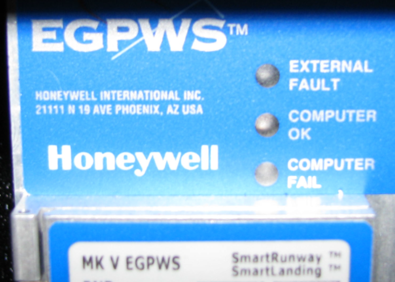
Also, TAWS reports faults through self-test, and gives, when necessary, applicable EICAS messages. Fault reports are also done with the maintenance diagnostic computer (MDC).
03/30/22
System Test
The system has power-up and continuous built-in test (BIT), and a test that the user can start. The test is started manually through the switch on the SYSTEMS TEST control-panel installed in the flight compartment (the aircraft must be on the ground). Several levels of data can be given through voice annunciations if the test switch is pushed. The test sequences are as follows.
Level 1 - Go/No Go Test
This sequence is an indication that the system can do all of its functions as per the TAWS configuration. For this sequence, the visual annunciations are shown and voices messages are given as an indication of which functions operate correctly. For example, if there are no faults on an installation that uses the terrain awareness function (in addition to basic GPWS and windshear), the typical result of the self-test would be:
GLIDESLOPE----PULL UP-----WINDSHEAR WINDSHEAR WINDSHEAR----TERRAIN TERRAIN PULL UP.
But, if there was no valid glideslope input, then the sequence would be:
GLIDESLOPE INOP-----PULL UP-----WINDSHEAR WINDSHEAR WINDSHEAR----TERRAIN PULL UP.
A terrain picture is shown on the MFD to do a test of the terrain display. During system self-test all INOP type annunciations are activated.
Level 2 - Current Faults
This sequence gives annunciations for all faults (if there are faults) that currently exist. It makes the difference between internal and external faults. If there are no faults, then the message GPWS COMPUTER OK is heard in the flight compartment loudspeakers.
Level 3 - Configuration Information
This sequence gives the versions of the hardware and software installed, and the data bases versions.
Also given are the current configuration item selections from the configuration module. This includes voice and callouts menus selections.
Level 4 - Fault History
This sequence gives annunciations for all system faults that were recorded for the last ten flight legs. (There is an access to data on the last 64 legs through the RS-232 interface).
Level 5 - Warning History
This sequence gives annunciations for all TAWS alerts that were recorded for the last ten flight legs. (There is an access to data on the last 64 legs through the RS-232 interface).
Level 6 - Discrete Input Test
This sequence gives annunciations for discrete input transitions to help in system installation and maintenance.

10/19/20