03/06/25
Overview
The Runway Overrun Awareness and Alerting System (ROAAS) (if installed) is a feature of the TAWS computer that complements flight crew’s situational awareness to the possibility of exceeding the runway end during approach and landing. It is designed to be an added safety net for runway overrun hazards. ROAAS provide alerts to the flight crew when areal−time calculation of landing distance exceeds the remaining available distance to the end of the runway. ROAAS landing distance is representative of the Factored Operational Landing Distance (FOLD), not the AFM Actual Landing Distance (ALD).
ROAAS is automatically armed during the approach and is comprised of two modes of operation:
- In-Air Mode
- On-Ground Mode

03/06/25
TAWS Computer
03/06/25
ROAAS Controls
The controls associated with ROAAS are located on the TAWS WARN/Landing Gear control panel.
Note:
The configuration of the TAWS WARN control panel may differ based on selected options (RAAS, STEEP APPR).

ROAAS Switch
The ROAAS PBA switch allows the pilot to inhibit alerts. The white OFF light is illuminated when OFF is selected (pushed in). The white OFF light extinguishes when the switch is selected again for normal function (pushed out).
ROAAS RCC 5 Switch
The RCC 5 PBA switch allows the crew to select ROAAS calculations to be based on braking characteristics equivalent to RCC 5. The white RCC 5 ON light is illuminated when selected (pushed in) indicating that RCC 5 has been selected. The RCC 5 ON light extinguishes when the switch is selected again (pushed out) for normal function (RCC 6).
03/06/25
System Interface
The TAWS Computer receives data from the following systems:
| System | Data |
|---|---|
| FMS | Gross weight, true track angle |
| GPS | Latitude, longitude, ground speed, altitude,GNSS height, true track angle, GNSS vertical and horizontal position errors (HFOM/VFOM) |
| IRS | Inertial vertical speed, ground speed |
| ADS | Pressure altitude, true airspeed, static air temperature |
| Landing Gear | Main gear Weight on Wheels (WOW) |
| Flaps | Flap lever in landing configuration |
| Engine | Engine N1 RPMs, Thrust Reversers status |
| Brakes | Brake pressures |
| Radio Altimeter | Radio height |
| Flight Guidance System | FG coupled side, vertical go−around |
The inputs are used to compute the required ROAAS Alerts. Additionally, the ROAAS System uses the TAWS runway database for its available runway length computations FG coupled side, vertical go−around.
03/06/25
Indications
ROAAS visual alerts are displayed on the center of the PFD. The visual alerts are:

Each of the ROAAS visual alerts will flash for five seconds when first displayed, then remains steady. When a ROAAS visual alert is displayed, it will also be accompanied by a corresponding aural.

03/06/25
System Monitoring
CAS Messages
| MESSAGE | INHIBITS | DESCRIPTION |
|---|---|---|
| ROAAS FAIL | TO/LAND | ROAAS failed (Internal software failure, input signal failure) |
| ROAAS NOT AVAIL | TO/LAND |
ROAAS is not available. ROAAS NOT AVAIL will be displayed and ROAAS alerts will not occur for the following scenarios:
|
| ROAAS/ RAAS FAIL | TO/LAND | ROAAS and RAAS (if installed) failed |
| ROAAS/ RAAS NOT AVAIL | TO/LAND | ROAAS and RAAS are not available |
| ROAAS OFF | ROAAS PBA (switch) is set to OFF (ROAAS is inhibited) | |
| ROAAS RCC 5 ON | ROAAS RCC 5 PBA (switch) is set to ON (RCC 5 has been selected) | |
| ROAAS/ RAAS OFF | ROAAS and RAAS PBAs (switches) are set to OFF (ROAASand RAAS are inhibited). |
Note:
TAWS SYSTEM FAILCAS message also means ROAAS and RAAS (if installed) have failed.
03/06/25
System Operation
The ROAAS system is active by default and arms within 4.5 nm and less than 1000 feet above destination runway. To allow inhibition of ROAAS alerts, the ROAAS may be turned OFF (inhibited) via the ROAAS switch/light located on the ROAAS control panel.
Runway Selection Criteria
ROAAS uses aircraft position and actual track to select the intended runway. The aircraft track must be within 20° of the runway extended centerline.The runway selection scan is automatic and independent of FMS inputs. The runway parameters used for runway selection are retrieved from the TAWS runway database. For a runway to be eligible for ROAAS runway selection, it must be a ROAAS−enabled airport and minimum runway length is 3,000 feet.
Factored Operational Landing Distance (FOLD) FOLD is the basis on which ROAAS was designed to be used. The ROAAS uses condition code 6 and 5 only.
ROAAS Model Distance (RMD)
The ROAAS Model Distance (RMD) is a real−time continuously calculated distance required for the aircraft to land and come to a stop which is internally computed by the ROAAS system. It blends performance data with real−time parameters such as groundspeed, height above the glideslope/glidepath, landing weight, runway condition selection (ROAAS RCC 5 switch) and runway information retrieved from the TAWS runway database. The RMD model is based on the maximum use of decelerating devices, such as maximum braking, maximum reverse thrust and the use of ground lift dumping.
Should the RMD be longer than the remaining available runway length, the ROAAS system will generate the applicable Visual and Aural alerts. There are two levels of In−Air Alerts:
- CAUTION Alert (Amber)
- WARNING Alert (Red)
The level of Alert will depend on the height above runway elevation.
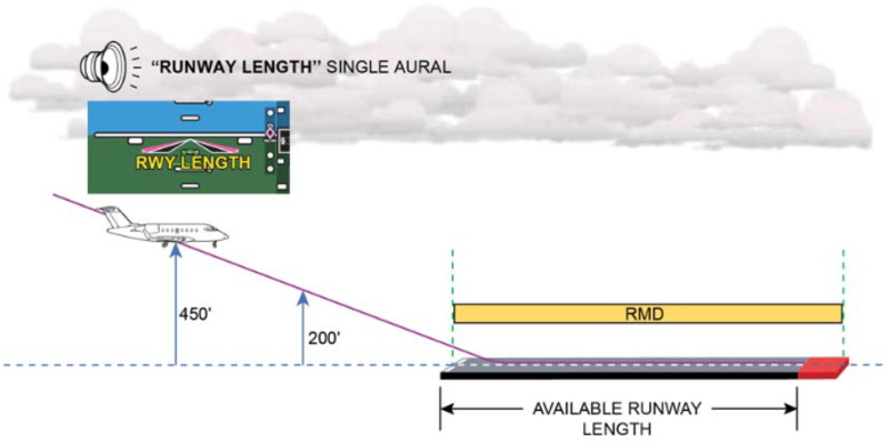
IN-AIR CAUTION
- Displayed when RMD is longer than the available landing distance
- Active during caution threshold zone (from 450 to 200 feet above runway elevation)
In−Air Mode CAUTION Alert − RMD Exceeding Available Runway Length:
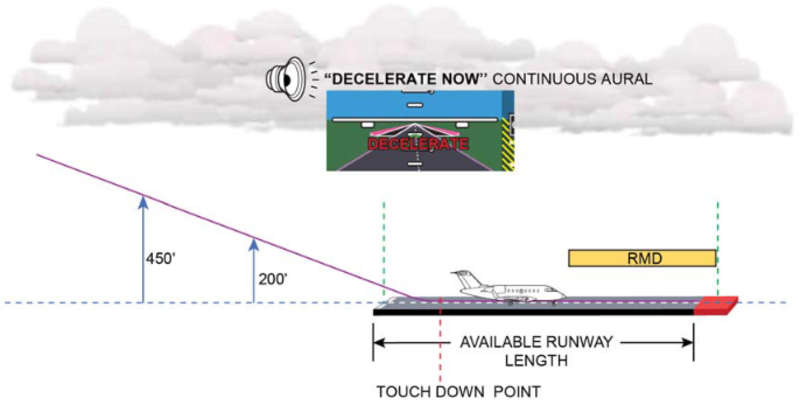
IN-AIR WARNING
- Displayed when RMD is longer than the available landing distance
- Active during warning threshold zone (200 feet above runway elevation to touch down)
In−Air Mode WARNING Alert − RMD Exceeding Available Runway Length:
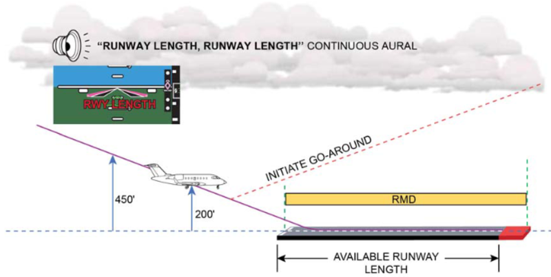
GO−AROUND
In the event of a go−around, balked landing or touch and go, ROAAS will automatically disarm. ROAAS is not re−armed until the aircraft climbs above 500 feet.
ON−GROUND MODE
The On−Ground Mode provides the flight crew with Visual and Aural Alerts during the roll out phase of the landing. On−Ground alerts can be activated between touch down and 40 knots groundspeed. ROAAS continuously monitors its RMD and sensed deceleration which is compared to the remaining available runway length. ROAAS will automatically disarm when the aircraft taxis off the runway (no longer aligned with runway) or when the ground speed is less than 40 kts. Existing ROAAS alerts will clear below 25 kts ground speed.
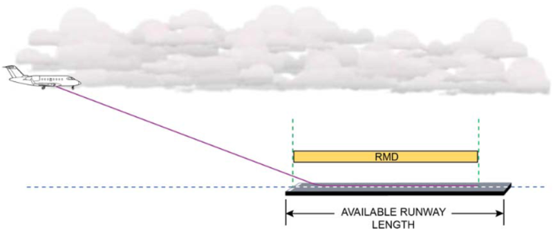
On−Ground Mode − No ROAAS Alerts:

Should the RMD exceed the remaining available runway length, the ROAAS system will generate the applicable Visual and Aural alerts. There are two levels of On−Ground Alerts:
- CAUTION Alert (Amber)
- WARNING Alert (Red)
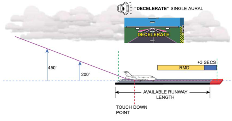
ON-GROUND CAUTION
Displayed when both of the following conditions apply:
- 3 seconds prior to when RMD is longer than the available landing distance
- Predicted stopping point (based on sensed deceleration) is at or beyond the end of the runway
Active between touch down and 40 kts ground speed.
Note:
Failure to increase deceleration could lead to a ROAAS Warning
On−Ground Mode − CAUTION Alert − RMD +3 Seconds and Predicted Stopping Point Exceeding Available Runway Length:
ON-GROUND WARNING
- Displayed when RMD is longer than the available landing distance
- Active between touch down and 40 kts ground speed
On−Ground Mode − WARNING Alert − RMD (No Lead Time) Exceeding Available Runway Length: