


01/28/16
Overview
The full authority digital electronic control (FADEC) system supplies control and monitoring functions for the engines. The system makes sure that the engine operates within the power plant limits. The FADEC system supplies the functions that follow (during usual operation or during engine or FADEC fault conditions):
- Controls engine thrust
- Adjusts engine speed
- Controls and monitors engine fuel feed system during:
- Startup
- Steady state
- Transient
- Normal and overspeed shutdown
- Controls the compressor variable geometry(CVG)
- Controls the ignition system
- Controls the bleed air
- Monitors engine oil system
- Monitors engine vibration
- Detects engine fault condition
- Controls the engine condition and monitors the trend
- Transmits engine parameters and fault condition data for display
- Controls engine synchronization
Also, the FADEC system controls the thrust reversers (TRs), with input from the landing gear system and throttle quadrant. Logic used by the FADEC controls TR operation, to prevent inadvertent deployment by the power plant.

05/20/22
Throttle Lever Quadrant
Throttle Lever Quadrant (TLQ) (A/C 20875 to 20936 pre SB350-22-002)
The TLQ is installed in the center pedestal of the flight compartment. It is an assembly consisting of:
- Throttle levers
- Gust lock lever
- Engine run switches
- Forward balk solenoid
- Reverse balk solenoid
- Rotary variable differential transformers (RVDT)
The two throttle levers are isolated electrically and mechanically. The throttle quadrant lets the flight crew control the engine power positions.
Each throttle lever operates two rotary variable-differential transducers (RVDT) which are installed on the throttle pivot in the center pedestal. The RVDTs supply throttle-lever position data to each of the engine electronic control units (ECU).
The FADEC system controls the thrust supplied by the engines and operates as an N1 controller. The RVDT of the throttle lever measures the throttle position and supplies an input to the engine ECUs.
The throttle moves through an 80 degrees range that is between -26 degrees and +54 degrees. The forward idle position is at 0 degree. The position of the throttle is a function of the throttle lever angle (TLA). Positive throttle positions are forward thrust and negative throttle positions are reverse thrust.
There are two ENGINE RUN switches that provide control for engine start and shutdown.
Throttle Quadrant Functions
The throttle quadrant provides the following functions:
- Supplies forward and reverse thrust controls to the FADEC
- Supplies engine shutdown signal to the FADEC and to the boost pump
- Supplies a go-around (GA) signal to the engine ECU
- Supplies a thrust reverser deployment signal to the engine ECU
- Supplies thrust idle positions to the engine ECU
- Locks the ailerons with a gust lock
- Locks the throttle levers at forward idle to prevent the selection of forward thrust if the reversers are not fully stowed
- Locks the throttle levers at reverse idle to prevent the selection of reverse thrust if the reversers are not fully deployed
- Locks the throttle lever in forward idle if the gust lock is engaged ON)
- Supplies an interlock mechanism, which lets the pilot lift the reverser levers at forward idle only
- Adjusts the friction for the throttle levers
- Supplies throttle notches to set the throttle levers at the following positions:
- Maximum reverse
- Reverse idle
- Climb
- Takeoff
- Automatic power reserve
- Supply engine start

Autothrottle (TQA) (A/C 20875 to 20936 post SB350-22-002, and A/C 20937 and Subs)
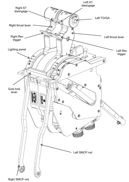
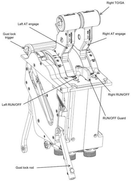
The TQA is installed in the cockpit center pedestal. It provides the pilot and co-pilot with means to run and shut down the engines, control engine thrust, operate the thrust reversers and engage and disengage the autothrottle. In addition, the TQA assembly includes a gust lock, that allows the flight controls to be locked preventing damage from wind gusts while the aircraft is parked. The left and right levers and the gust lock are housed in 3 independent sections of the TQA.
Each thrust lever module includes a thrust lever, a reverser trigger, an engine run/off switch, a TO/GA button, an AT disengage button and a AT engage paddle. Additionally, each module is connected to its respective side of the autothrottle Servo Motor Clutch Pack (SMCP) via a rod. The gust lock module includes a gust lock lever and a gust lock trigger. A gust lock rod is used to connect the module with the aircraft gust lock system. The top portion of the TQA has a lighting panel and a guard between the 2 run/off switches.
Each thrust lever is connected to dual RVDT position sensors and to a total of 8 switches which are defined below:
- Dual idle switches used by the Spoiler Electronic Control Unit (SECU) for the auto-arming function of the ground lift dump system.
- Dual reverse switches used by the thrust reverser system as one of the inputs to command a deployment.
- A TO/GA switch
- An autothrottle (AT) engage switch
- An autothrottle disengage switch
- A dual pole engine run/off switch
The TQA also includes one forward and one reverse balk solenoid per module, connected in line with one current limiter each (total of 2). A single board including one relay per side receives and combines the signals from each side idle switches before outputting them to the aircraft systems. Four connectors at the bottom of the assembly connect the unit to aircraft wiring and are used for all input and output signals.
Two TQA connecting rods are fastened to the SMCP, which is installed at the cockpit floor inside the center pedestal. A separation plate is installed as part of the aircraft structure to ensure separation between the left and right rods in case of a mechanical failure of either connecting rod. (Refer to 22-30-00 for more information).
01/28/16
Electronic Control Unit
The engine electronic control unit (ECU) is the primary control unit of the FADEC system. It controls engine thrust in relation to power positions, as set on the throttle quadrant. It also uses flight data (ground, flight, approach) and the difference between the two engines to set engine thrust.
There are two engine ECUs for each of the engines (channel A and channel B). They are installed on the frame of the outer fan of the engine. Air inlets in the fan cowl doors keep the engine ECUs cool.
There is an RS 422 data link between the engine ECUs on the same engine (cross-channel) and between the engine ECUs on the opposite engines (cross-engine). This configuration prevents a loss of function in the event of a fault condition of a redundant component.
The engine ECUs continuously monitor all inputs, calculate all outputs, and transmit all data signals. There is a primary engine ECU and a secondary engine ECU. When the primary engine ECU controls the engine, the outputs of the secondary engine ECU are disabled. The outputs of the secondary engine ECU are always available and automatically control the engine if the primary engine ECU can not.
The engine ECUs use the RS 422 data link to do checks for a fault condition. Each of the engine ECUs transmits its operating condition to the other engine ECU. The FADEC system compares this data to give control to the more serviceable engine ECU.
The primary engine ECU automatically changes with each engine start. The engine ECU in control on engine shutdown does the subsequent engine start. The other engine ECU becomes the primary engine ECU in control when the engine reaches 45% N2. During operation of the engine, changes in control occur only when there is a fault condition in the primary engine ECU in control.
The left and right essential buses supply 28 VDC to the engine ECUs. When the engine reaches 45% N2, the PMA becomes the primary source of power for the engine ECUs.


Permanent Magnet Alternator
The permanent magnet alternator (PMA) is mounted on the aft side of the accessory gearbox.
The permanent magnet alternator (PMA) supplies the required three-phase electrical power for each engine ECU at and above 45% N2. Aircraft power is required to start the engines. At 45% N2, the PMA becomes the primary source of power. The engine ECU logic is designed to select the highest voltage provided between the aircraft essential bus and PMA
The PMA has a case which contains two sets of coils, an isolated pair of windings, and a rotor that is a permanent magnet. The permanent magnet is attached to a shaft in the accessory gearbox. Each of the windings supplies a power source and an N2 speed signal to each of the engine ECUs.
Gears and shafts in the engine turn the accessory gearbox which turns the rotor. While the rotor turns, it induces current in each of the two sets of coils. At low rpm, the three-phase output is approximately 20 VDC. At high rpm, the three-phase output is approximately 80 VDC.


01/11/16
Operation
FADEC System
The FADEC system controls the thrust supplied by the engines and operates as an N1 controller. The RVDT of the throttle lever measures the throttle position and supplies an input to the engine ECUs. This is the primary input for the N1 TLA reference point.
The FADEC system uses engine performance data to apply control parameters. N1 is the low-pressure inlet fan speed from the engine. N1 input is the primary control indicator when the engine is above idle. N2 is the high-pressure core/gas generator speed from the engine. N2 input is the primary engine control indicator when the engine is at idle. N1 and N2 maximums also supply continuous engine control.
All critical sensors and actuators which interact with the FADEC system are dual element, one element for each channel. The FADEC system shares all sensor data between channels for enhanced reliability.
Engine sensors usually have two windings. The torque motors have two coils to control the actuators for the engine. Dual element sensors supply the FADEC with the following input:
- N1 speed
- N2 speed
- TT2
- PMA N2 speed
- Fuel flow
- Low oil pressure
- EGT
Note:
The engine ECU gets N2 speed input from the PMA as well as the N2 monopole speed sensor.
The two engine ECU channels in the FADEC system supply continuous control to make sure the system operates correctly. When the FADEC system has an internal fault condition, it changes to a secondary sensor or signal and there is a loss of redundancy. This lets FADEC control continue with no change in thrust or engine operation. A signal is sent from the engine ECU to the data concentrator unit (DCU), which sends a L(R) ENGINE MINOR FAULT advisory message that shows on the EICAS.
An engine control malfunction can occur which could prevent a take-off after the subsequent landing. If this occurs, a signal is sent from the engine ECU to the DCU, which sends a L(R) ENGINE FAULT advisory message that shows on the EICAS.
An aircraft/engine control system could have a malfunction which will cause small changes to the engine thrust. If this occurs, a signal is sent from the engine ECU to the DCU, which sends a L(R) ENG THRUST FAULT advisory message that shows on the EICAS.
If the secondary sensor or signal also becomes defective, the FADEC system changes to an alternative mode of operation. Thrust control decreases and maximum engine power decreases. A signal is sent from the engine ECU to the DCU to display a L (R) FADEC FAIL caution message on the EICAS.
If the FADEC system becomes more defective, it sets the engine speed at one low-power position and changes in TLA have no effect. If the system becomes unserviceable, the engine is stopped, and all starts are prevented. Before a change to an alternative mode occurs, the FADEC system verifies sensor input to ensure the mode change is necessary.
Each engine ECU protects from an overspeed condition caused by too much fuel in the control system. The protection circuits in each of the engine ECUs are isolated from each other. They can stop the supply of fuel when an overspeed condition occurs. The FADEC uses N2 as an input for protection from an overspeed condition.
Fan speed is scheduled as a function of altitude, temperature, Mach number, and aircraft bleed during aircraft flight. All the scheduled limits for engine acceleration use the engine operating conditions to ensure the engine has protection from surge in all flight conditions.
All the scheduled limits to decrease the engine speed keep the engine operating conditions within the permitted limits. The FADEC uses calculated airflow through the engine to set a minimum fuel flow in all flight conditions.

Engine Power Positions
There are seven engine power positions set as a function of the five throttle notches. These power positions are set to ensure the engine has a high performance output for flat rate and maximum speed conditions. The power positions are as follows:
Automatic Power Reserve
The APR function automatically adjusts the thrust position when an engine fault occurs during takeoff. The flight crew can override the automatic thrust adjustments with the AUTO APR OFF switch on the ENGINE control panel. Selection of AUTO APR OFF prevents the automatic change to APR (and MCT) if one engine is not available. When AUTO APR OFF is selected, an AUTO APR OFF status message is shown on the EICAS.
APR automatically starts on either engine when the N2 speed difference is more than 15% and the throttle is at the CLB position. It can also be manually started when the throttle lever is pushed forward to the mechanical stop at +54 degrees. Full APR thrust is supplied up to the altitude of 20,000 ft (6,096 m) mean sea level (MSL). Between 20,000 (6,096 m) and 30,000 ft (9,144 m) MSL, APR thrust is linearly decreased to MCT.
When one engine not available causes an APR, the N1 maximum (red line) shows on the display for 10 minutes. The N1 red line shows for five minutes when the APR is set manually. At the end of the time limit, the red line value is decreased, and the values that were above the limits are recorded by the engine ECU. The thrust supplied by the engine does not change at the end of the APR power time limits.
Takeoff
Takeoff (TO) supplies a flat rate of thrust to ISA+15 °C (59 °F) at sea level. Takeoff thrust is available up to an altitude of 20,000 ft (6,096 m) MSL. Between 20,000 ft (6,096 m) and 30,000 ft (9,144 m) MSL, TO thrust is linearly decreased to climb thrust.
Total air temperature, altitude Mach number, bleed status, and status between engines calculates N1 for maximum climb.
Maximum Continuous Thrust
The maximum continuous thrust (MCT) starts with the throttle at the CLB position, an engine not available, and the auto APR function on.
Climb
Maximum climb (CLB) power starts when the throttle is set to the CLB position. Total air temperature, altitude Mach number, bleed status, and the status between the engines calculates N1 for maximum climb.
Cruise
Cruise (CRZ) power starts when the throttle is adjusted to the cruising speed (maximum cruise) or below. There is no one TLA position that supplies a maximum cruise N1. The CRZ N1 value is shown as a target on the N1 display. Maximum cruise N1 thrust is calculated on the same parameters as CLB.
Flight Idle
Flight idle is the lowest power setting available in flight. No reverse thrust is available when the aircraft is in flight.
Ground Idle
On the ground, idle thrust starts when the TLA is at 1.5%. Thrust increases linearly when the throttle is moved forward to the CRZ position.
Reverse Idle
On the ground, reverse thrust starts when the throttle is moved back to a TLA of –6%. A solenoid activated balk wall prevents the throttle from moving back further until the thrust reversers are fully deployed.
Landing Reverse
Landing reverse (LDGREV) thrust is the maximum corrected N1 that supplies 1,600 lbf (7,117.12 N) of reverse thrust. It is calculated at sea level, static, ISA+15 °C conditions, at the MAX REV throttle position. The corrected N1 that gives this thrust changes with altitude and is used for all usual landing conditions.
Rejected Takeoff
Rejected takeoff (RTO) thrust is the maximum corrected N1 that supplies 2,200 lbf (9,786.04 N) of reverse thrust. It is calculated at sea level, static, ISA+15 °C conditions, at the MAX REV throttle position. FADEC logic sets this thrust for rejected takeoff conditions and changes with altitude.


Engine Electronic Sensors
The engine ECU uses data from sensors installed in the power plant and data from the air data computer (ADC). The ADC supplies data to the engine ECU through the ARINC data bus. The engine ECU calculates some of the parameters with the data from the sensors. The engine ECU uses these parameters to control engine operation.
The engine ECU receives inputs from the air data computers to calculate:
- Total air temperature (TAT)
- Computed air speed (CAS)
- Mach number (MN)
Three N1 sensors measure low pressure (LP) rotor speed. Each of the engine ECUs uses one isolated sensor (coil). The third sensor (coil) is used by both engine ECUs. Each of the engine ECUs has access to all three N1 signals through the cross-channel data link.
Four N2 sensors measure high pressure (HP) rotor speed. Each of the engine ECUs uses two isolated speed sensors. Each of the engine ECUs has access to all four N2 signals through the data link.
There are eight exhaust gas temperature (EGT) probes in the control system. The average is calculated from four EGT outputs and is sent to one engine ECU.
The average from the other four EGT outputs is sent to the second engine ECU. Each of the engine ECUs has access to all eight EGT signals through the data link. The engine ECU uses the measured EGT, N1, and N2 to give an interstage turbine-temperature (ITT) value. This value shows on the engine indicating and crew alerting (EICAS) display in the flight compartment.
The inlet temperature (TT2) sensor supplies fan inlet temperature signals to the engine ECU. Ambient temperature is calculated from the TAT and MN.
The pressure sensors for nacelle ambient pressure (P0) and compressor discharge pressure (P3) are integral to each engine ECU.
The engine ECUs receive the output from the vibration sensor, which is attached on the engine front frame. This signal shows on the EICAS in the flight compartment and is also used by the engine ECU for ground-based fan trim balance.


Automated Control Features
There are engine control functions where a small quantity of input or no input from the pilot is necessary. These functions include N1 adjustment, primary engine selection, engine synchronization, and Mach hold.
N1 Adjustment
The N1 adjustment value for the engine is calculated with a test during engine production. A small compensator module is permanently attached to all engines with an internal resistor value. This value is the N1 adjustment value. It is the number of rpm, below the rated rpm, that the engine can turn to have the rated thrust. An engine that turns at 9,800 rpm N1 when the rated thrust is 10,000 rpm has an N1 compensator of 200 rpm.
The compensator module is connected to the two engine ECUs. Each of the resistors is connected to one engine ECU. The N1 adjustment value is added to the engine ECU measurement of N1 at the time of measurement. All engine control functions that use the measured N1 value use the adjusted N1 value.
Primary Engine Selection
The left and right engines automatically make one engine a primary engine and one engine a secondary engine. The engine with the higher N1 adjustment is the primary engine. If the N1 adjustment is the same for the two engines, the left engine becomes the primary engine.
Engine Synchronization
The flight crew has engines synchronized through the AUTO SYNC switch on the ENGINE control panel. The three positions are N1, N2, and OFF. The signal from the AUTO SYNC switch is transmitted to the engine ECU through the ARINC data bus. When SYNC (N1 or N2) is set, the two engines are synchronized on speed if the two engines show cruise (CRZ) or climb (CLB) on the display. If a fault occurs preventing engine synchronization, an ENGINE SYNC FAIL advisory message is shown on the EICAS.
The secondary engine uses the N1 TLA set point from the primary engine as its set point. The engines are synchronized when the N1 TLA set point from the primary engine equals ±5% of the measured N1 from the secondary engine. If the difference is more than 5%, the secondary engine will try to synchronize.
For N2 synchronization, the difference between the secondary engine N2 and primary engine N2 is added to the N1 set point. The engines are synchronized when the difference between N2 of the two engines is ±5% N1. If the difference is more than 5%, the secondary engine continues to try synchronization.

Mach Hold
The FADEC system supplies the Mach hold function. This function holds the Mach selection by changes to engine power. The Mach hold function is only done on the primary engine. The secondary engine follows the primary engine through synchronization. The Mach hold function is available only when the altitude hold function is on and the altitude captured, and N1 or N2 synchronization is on. The pilot controls this function through the MACH HOLD switch on the ENGINE control panel. If a fault occurs preventing engine Mach hold function an ENG MACH HOLD FAIL advisory message is shown on the EICAS.

Engine Condition Trend Monitoring
The engine ECU has an ECTM function. The ECTM continuously records and monitors engine parameters. The purpose of the ECTM function is to increase the effects of maintenance, increase engine life, and decrease maintenance time. The engine ECU ECTM display function supplies system status data for the EICAS messages.
ECTM Functions
The functions of the ECTM are to:
- Monitor and record the performance of the power plant
- Count the life cycle of the power plant system
- Monitor component life
- Record unserviceable conditions below the LRU level
- Report LRU level fault conditions
- Calculate the performance status of the power plant
- Keep a file of fault conditions for the engine and engine control system
- Find and record the conditions that are out of the power plant range of operation
- Record functions that are started automatically, or by the pilot
- Record the number of aircraft and engine operations
- Monitor engine vibration
- Monitor the lubrication system
- Do a fault isolation of applicable power plant fault conditions
- Do a fault analysis of the power plant to decrease unscheduled maintenance
- Supply storage of ECTM data for a minimum of 100 flights before a data download is necessary
When necessary, on ground, a DOWNLOAD FADEC advisory message is shown on the EICAS prompting maintenance personnel to collect data from the FADEC system.
If the left (right) engine flames out, a L (R) ENGINE FLAMEOUT caution message is shown on the EICAS. When OFF is selected on the L (R) ENGINE switch on the throttle, or when the L(R) ENG FIRE push button annunciator (PBA) is selected on the engine control panel, the engines shut down and a L (R) ENGINE SHUTDOWN status message is shown on the EICAS.
Fault Indication
The engine ECU ECTM function supplies fault condition data to the maintenance diagnostic computer (MDC). The engine ECU ECTM function makes sure of a fault condition before it sends the data.
The FADEC system will remove all fault indications when the engine ECU is energized. When a fault condition removal is completed, a built-in test (BIT) is done by the engine ECUs.
The EICAS messages that follow are related to the FADEC system:
|
EICAS MESSAGE(S) |
LEVEL (COLOR) |
|---|---|
|
L ENGINE FLAMEOUT |
CAUTION (amber) |
|
R ENGINE FLAMEOUT |
CAUTION (amber) |
|
L FADEC FAIL |
CAUTION (amber) |
|
R FADEC FAIL |
CAUTION (amber) |
|
DOWNLOAD FADEC |
ADVISORY (cyan) |
|
ENG MACH HOLD FAIL |
ADVISORY (cyan) |
|
ENGINE SYNC FAIL |
ADVISORY (cyan) |
|
L ENGINE FAULT |
ADVISORY (cyan) |
|
R ENGINE FAULT |
ADVISORY (cyan) |
|
L ENGINE MINOR FAULT |
ADVISORY (cyan) |
|
R ENGINE MINOR FAULT |
ADVISORY (cyan) |
|
L ENG THRUST FAULT |
ADVISORY (cyan) |
|
R ENG THRUST FAULT |
ADVISORY (cyan) |
|
AUTO APR OFF |
STATUS (white) |
|
L ENGINE SHUTDOWN |
STATUS (white) |
|
R ENGINE SHUTDOWN |
STATUS (white) |


EC-FR Data Download
Downloading EC–FR data from the engine ECUs is accomplished with a personal computer (PC), Honeywell Electronic Engine Interface (EEI) software, and the EC–FR data cable (EDC) through data ports on the aircraft. Both the EEI software and the EDC are provided to operators by Honeywell. In addition to downloading data, the EEI and EDC initialize engine ECU/engine/aircraft parameters whenever an engine ECU is replaced, viewing EC–FR maintenance condition data without downloading, and as an engine maintenance and test aid.
The download function allows the transfer of EC–FR data from the engine ECU to the PC. During download, all data is stored to a fixed location on the PC hard drive. A backup copy can be saved to another location at the operator’s discretion.
When the operator wishes to perform a download, or use any of the other EEI capabilities, the EEI software launched from the PC. The EDC is then connected to the PCMCIA slot of the PC and to the maintenance data ports on the aircraft. The engine must be on the ground and not running before the user may initiate a download through the EEI. Performing the download is conducted by following the Light Maintenance Manual(LMM) and onscreen directions.
If an engine ECU or engine is replaced at a location where an EEI-equipped PC is not available and EC–FR data is not downloaded prior to removal, the EEI has provisions for downloading a removed engine ECU or dismounted engine. This is performed using a special data cable and power cable that interface directly with the engine ECUs. The engine ECUs must be powered by an external power supply.

Alternate Download Method
If a laptop is not available, and is necessary to download fault data for troubleshooting purposes, the avionics system data base unit (DBU) can be used.
This procedure allows for the download of all stored data in the MDC to a 3.5" floppy disc. This data is saved in a text format that can be easily read using Microsoft Word or WordPad, located in the accessories menu of the Windows operating system.
The following steps are required to accomplish the download:
- Access the MDC MAINTENANCE MAIN MENU display page
- Select submenu REPORT DOWNLOAD and press ENTER
The REPORT DOWNLOAD submenu will have two submenus to choose from. Select MDC REPORT DOWNLOAD and press ENTER.
Now the FILE TYPE can be highlighted using the JOYSTICK. When the appropriate file is highlighted, press ENTER and the download will begin.
Note:
Alternative method does not allow to download engine ECU NVM. Only MDC information related to engine ECU can be downloaded.

01/09/16
System Interface
The FADEC system interfaces with the following systems/components:
- Engine Nacelle Anti-Ice
- Air Data System
- Fuel Distribution System
- Hydromechanical Unit (HMU)
- Fuel Indicating System
- Ignition System
- Engine Control Panel
- High-Pressure (HP) Compressor-Airflow Control
- Emergency Shutdown
- Speed Sensing
- Temperature Sensing
- Vibration Sensing
- Control and Feedback System
- Oil Distribution System
- Oil Indication System
- Air Turbine Starter
System Test
Fault Detection
Hardware and software diagnostic tests supply detection of a fault condition in the power plant. These BIT tests are done continuously during usual control system operation. They are also done during cold boot, warm boot, and when the engine starts and stops. Cold boot is when an engine ECU is energized with the engine stopped (N2 below 2%). Warm boot is when an engine ECU is energized during engine operation.
Each of the BIT tests done is either a BIT that latches or a BIT that does not latch. The BIT that latches keeps the indication of a fault condition in memory, even if the signal goes back to a serviceable condition. All of the indications of a fault condition are removed when the FADEC system is de-energized. The BIT tests that do not latch keep the indication of a fault condition during the time the input signal is in a fault condition. If the signal returns to normal operation, the BIT that does not latch indicates no fault.
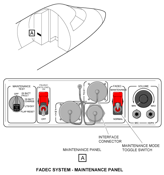
Maintenance Mode Operation
There is one maintenance panel located in the LH equipment rack. It gives the FADEC system an interface with ground support equipment (GSE).
The maintenance panel has a connector for the RS-422 interfaces, an N1 speed indication from each engine ECU, and an engine vibration output from each engine. The maintenance panel also has a four-pole switch to activate the maintenance mode on each engine ECU of the FADEC system.
When the maintenance switch is energized it prevents nuisance fault conditions during maintenance. It also lets the thrust reverser be energized for ground test functions.


10/28/20
Component Location Index
| Component Location Index | |||
|---|---|---|---|
| IDENT | DESCRIPTION | LOCATION | IPC REF |
| A51 | THROTTLE QUADRANT | ZONE(S) 210 | 76−10−01 |
| - | ELECTRONIC CONTROL UNIT (ECU) A (LH) | PANEL(S) 432DT | 76−10−05 |
| - | ELECTRONIC CONTROL UNIT (ECU) A (RH) | PANEL(S) 442AT | 76−10−05 |
| - | ELECTRONIC CONTROL UNIT (ECU) B (LH) | PANEL(S) 432AT | 76−10−05 |
| - | ELECTRONIC CONTROL UNIT (ECU) B (RH) | PANEL(S) 442DT | 76−10−05 |