

01/25/21
Message Overview:
Message Description:
The Left Generator has failed.
This CAS message will be posted when the following conditions occurs:
- L GEN SW is not turned OFF and L ENG is running AND;
- L GEN is not producing voltage between 24 V & 31.5 V OR;
- L GEN LINE CONTACTOR is not closed AND;
- Aircraft is not WOW OR;
- EXTERNAL DC CONTACTOR is not closed.
Possible Causes:
- L Main Generator (GEN)
- Generator Control Unit (GCU)
- #1GCU PCB Not Fully Seated into the DCPC
- Aircraft System Failure
- Electrical System Component(s)
- Associated Wiring
Troubleshooting Tips:
Advisory Wire/Service Bulletin:
- AW300-24-0073 - SB100-24-08 - Modification of DC Power Center (DCPC) - System Reactivation
- AW300-24-0085 - DC Generator Shaft Spline Wear/Corrosion
- AW300-24-0141 - Electrical System and Flight Display Issues During Flight
- AW300-24-0326 - Generator Control Unit PN R3608-005
Forum Articles/Infoservice/Newsletter: None
Quick Links:
| Removal of the Main Generator | AMM 24-31-05-000-801 |
| Installation of the Main Generator | AMM 24-31-05-400-801 |
| Operational Test of the Main Generator | AMM 24-31-05-710-801 |
| Removal of the Generator Control Unit (GCU) - Primary | AMM 24-31-13-000-801 |
| Installation of the Generator Control Unit (GCU) - primary | AMM 24-31-13-400-801 |
| Wiring - Maintenance Practices - ALL | SPM 20-12-00-02 |
| Wire Repair - Maintenance Practices - ALL | SPM 20-12-10-02 |
Troubleshooting Recommendations:
- Interrogate the MDC as follows:
- On the cursor control panel, ensure the toggle switch is to the right and select Anti-Ice, ECS and Fuel buttons simultaneously. The MDC main menu should now be displayed on Display Unit #3.
- Using the joystick, select Current Faults (if the fault is active) or Aircraft History to research stored faults. From Aircraft History you can then select Fault Message History and locate the fault.
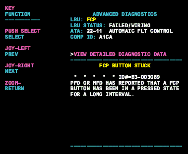
- Check advanced diagnostics for the generator fault, select the MDC equation or nomenclature from the drop down below to provide additional information to assist in troubleshooting.

NOTE: In the event that no MDC faults are posted, please note that the DC Generator, the Generator Line Contactor (GLC) and the Generator Control Unit can be swapped for troubleshooting purposes.