

03/26/25
Message Overview:
| DDG Reference: | 28-41-02 |
| Pilot Action (QRH): | FUEL 09-4 |
| System Description: | 28-41-00 - Fuel Management And Quantity Gauging System (FMQGS) |
| Schematic Diagram: | SSM 28-41-00-101 - Fuel Management and Quantity Gauging System (FMQGS) |
| Wiring Diagram: | WM 28-23-01-1_001 - Sheet 1 - Refuel/Defuel Control Panel - ALL WM 28-41-01-1_001 - Sheet 1 - Fuel Quantity Computer - ALL WM 28-41-13-1_001 - Sheet 1 - Fuel Quantity Probes (LHS) - ALL WM 28-41-15-1_001 - Sheet 1 - Fuel Quantity Probes (RHS) - ALL WM 28-41-21-1_001 - Sheet 1 - Temperature Sensor - ALL |
Message Description:
The cyan 'FUEL QUANTITY FAULT' advisory Crew Alerting System (CAS) message indicates the left or right channel has detected a fault or loss of temperature compensation.
Possible Causes:
- Fuel System Computer Unit (A57)
- Remote Data Concentrator (RDC) (A13)
Troubleshooting Tips:
Advisory Wire/Service Bulletin:
- AW300-28-0118 - No Fault Found Initiative: Fuel Quantity and Gauging Computer (FQGC)
- AW300-28-0138 - Fuel Tank Sumping
- AW300-28-0398 - SmartFix Plus Fuel System Troubleshooting Updates
Full Throttle Blog/Forum Articles/Infoservice/Newsletter: None
Flight Operation Notifications Manual (FONM): None
NOTES:
- Because water has a higher dielectric constant than fuel, water in fuel tanks will affect the reading of fuel quantity probes if it comes in contact with them. The reading will become out of range and the FQGC will stop sending fuel quantity for that tank (magenta dashes). At a certain point, enough water in a fuel quantity probe will 'short' the probe's concentric tubes and collapse the oscillator signal feeding all probes for that tank. The FQGC will identify the oscillator as faulty and will shut down the affected tank channel and identify the fault as internal to the FQGC (MDC code B3-006789).
- Before replacing the FQGC, make sure the failure is not caused by the presence of water contamination on fuel probes.
- When sumping water from affected fuel tank it is preferable to have fuel probes immersed in fuel, in order for the water to pool at the bottom of the fuel tank.
- To get most of the water to the bottom of the tank, for T/S purposes do not move aircraft for at least 2 hours before sumping.
- You can view and compare the Left wing and Right wing Fuel probe capacitance values via the MDC on the Fuel Probe Capacitance Display page. If one probe seems off compared to the other side, the affected probe may need to be cleaned.
- Fill the Detailed FQGC Troubleshooting Report if Fuel Quantity Gauging Computer (FQGC) pn 738360-1-2 is replaced.
Quick Links:
| Standard Aircraft Configuration for Maintenance | AMM 12-00-00-867-803 |
| Use of Fuel Biocide Additive When Pressure Refueling | AMM 12-11-01-620-801 |
| Pressure Refueling | AMM 12-11-01-650-801 |
| Use of Fuel Anti-Icing Additive When Pressure Refueling | AMM 12-11-01-660-801 |
| Suction Defueling | AMM 12-11-09-650-801 |
| Use of Fuel Biocide Additive When Gravity Refueling | AMM 12-11-13-620-801 |
| Gravity Refueling | AMM 12-11-13-650-801 |
| Use of Fuel Anti-Icing Additive When Gravity Refueling | AMM 12-11-13-660-801 |
| Microbial Growth Test | AMM 12-11-28-280-801 |
| Fuel-System Safety Precautions | AMM 28-00-00-910-801 |
| Cleaning of the Fuel Tank | AMM 28-10-00-160-801 |
| Biocide Treatment of the Fuel Tank | AMM 28-10-00-620-801 |
| Drain Water from the Fuel Tank | AMM 28-10-00-680-801 |
| Prepare Fuel Tank for Access | AMM 28-10-00-840-801 |
| Removal of Fuel Fumes | AMM 28-10-00-840-802 |
| Close the Fuel Tank after Maintenance | AMM 28-10-00-840-803 |
| General Visual Inspection of the Fuel Storage System | AMM 28-10-00-210-801 |
| Operational Check for Water in the Fuel | AMM 28-10-00-750-801 |
| Component Location | AMM 28-11-00-992-801 |
| Component Location | AMM 28-41-00-992-801 |
| Built-In Test of the Fuel-Quantity Gauging System | AMM 28-41-00-740-801 |
| Removal of the Fuel Quantity Computer | AMM 28-41-01-000-801 |
| Installation of the Fuel Quantity Computer | AMM 28-41-01-400-801 |
| Removal of the Fuel Quantity Probe | AMM 28-41-13-000-801 |
| Installation of the Fuel Quantity Probe | AMM 28-41-13-400-801 |
| Removal of the Fuel Quantity Probe with Compensator | AMM 28-41-13-000-802 |
| Installation of the Fuel Quantity Probe with Compensator | AMM 28-41-13-400-802 |
| Capacitance Check of the Fuel Quantity Probes | AMM 28-41-13-760-801 |
| Cleaning of the Fuel Quantity Probes | AMM 28-41-13-160-801 |
| Removal of the Remote Data Concentrator (RDC) | AMM 31-41-05-000-802 |
| Installation of the Remote Data Concentrator (RDC) | AMM 31-41-05-400-802 |
| Removal of the Input/Output Concentrator Unit (IOC) | AMM 31-45-05-000-801 |
| Installation of the Input/Output Concentrator Unit (IOC) | AMM 31-45-05-400-801 |
| Operational Test of the Input/Output Concentrator Unit (IOC) | AMM 31-45-05-710-801 |
| Data Download from the Maintenance Diagnostic Computer (MDC) | AMM 45-45-01-970-802 |
| Safety Precautions - Maintenance Practices - ALL | SPM 20-00-01-02 |
| Wire Repair - Maintenance Practices - ALL | SPM 20-12-10-02 |
| Electrical Connectors - Description and Operation - ALL | SPM 20-20-00-00 |
Troubleshooting Recommendations:
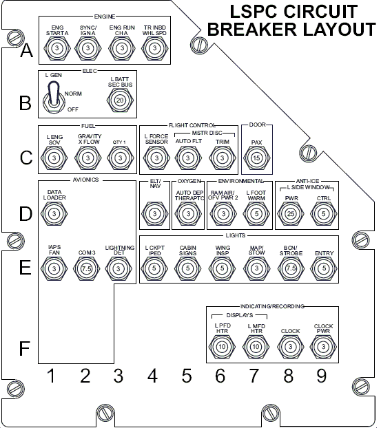
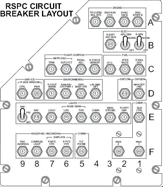
- Pull and reset the Fuel Quantity system breakers (CB3-C3, CB4-C3), recheck the system for the fault.
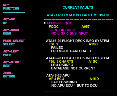
- Interrogate the MDC as follows:
- On the cursor control panel, ensure the toggle switch is to the right and select Anti-Ice, ECS and Fuel buttons simultaneously. The MDC main menu should now be displayed on Display Unit 3.
- Using the joystick, select Current Faults (if the fault is active) or Aircraft History to research stored faults. From Aircraft History you can then select Fault Message History and locate the fault. Going into advanced diagnostics will provide an equation id for the fault identified.
- Select the MDC fault or equation from the drop down below to provide additional information to assist in troubleshooting.
- Do close out.