03/18/26
Message Overview:
| DDG Reference: | 30-41 R WSHLD HEAT FAIL |
| Pilot Action (QRH): | ICE 12-9 |
| System Description: | 30-41-00 - Windshield And Side Window Anti-ice |
| Schematic Diagram: | SSM 30-41-00-101 - Windshield and Side Window Anti-Ice |
| Wiring Diagram: | 30-41-03 - Windshield Temperature Controllers (RHS) - ALL 30-41-11 - Windshield Heater Power-Supply (RHS) - ALL 30-41-13 - Windshield Heater DCU Interface - ALL 30-41-21 - Windshield Heater LO/HI Switching Enable - ALL |
Message Description:
The amber 'R WSHLD HEAT FAIL' caution CAS message indicates the respective windshield heat has failed and the temperature is too low or too high.
- The respective windshield controller (A157 LH, A158 RH) has sensed temperatures out of tolerance.
Possible Causes:
- Right Windshield (MPE56)
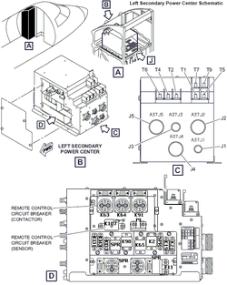
- Right Secondary Power Center (A38) Relay (K64)
- Right Secondary Power Center (A38) Time Delay Thermal Detector 70 Amp Relay (K106)
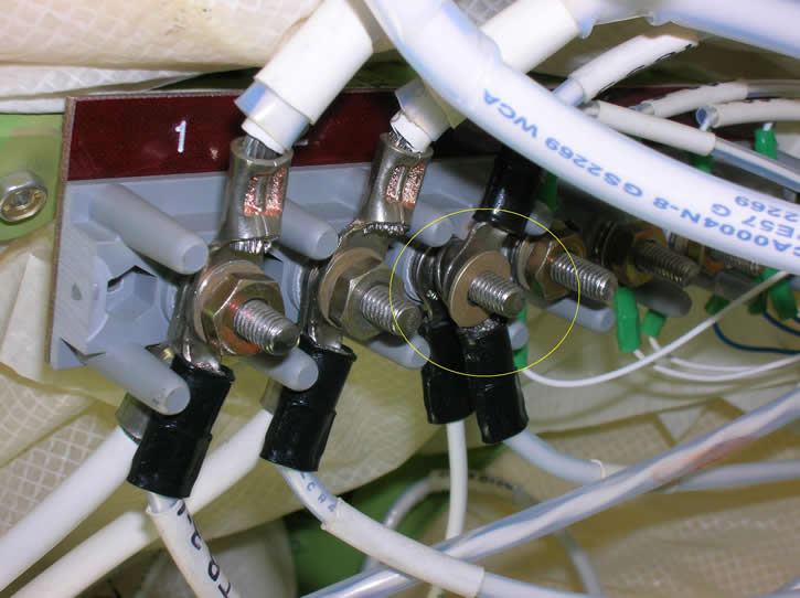
- Ground Stud (GS2270)
- Right Terminal Block 4
- Right Windshield Temperature Controller (A158)
- Associated Wiring
Troubleshooting Tips:
Advisory Wire/Service Bulletin:
- AW300-30-0328 - Windshield Heat Fail CAS Messages
- AW300-30-0418 - Windshield and Side Window Temperature Sensor Drift
Full Throttle Blog/Forum Articles/Infoservice/Newsletter: None
Flight Operation Notifications Manual (FONM): None
NOTES:
- The L and R Window Temperature Control circuits and parts (including relays) can be used for troubleshooting if needed (interchange).
- The Windshield Temperature Controllers and Side Window Temperature Controllers are different part numbers.
- In case of transparency removal, fill the "Transparency Return Form", send a copy to the CRC and attach a copy to the returned unit.
- The resistance of windshield sensor check (Rmin < normal resistance < Rmax) Maximum expected sensor resistance using the following formula: Rmax = 0.6*x + 275 Ω, where x is the ambient temp of the windshield in °F. Minimum expected sensor resistance using the following formula: Rmin = 0.8*x + 248 Ω, where x is the ambient temp of the windshield in °F, where °F= (°C * 1.8) + 32.
- The Windshield Sensing Element Curve (Temperature - Resistance Curve) is embedded in the Transparency Return Form, but also provided here for the users convenience.


Quick Links:
| General Setup for Maintenance | |
|---|---|
| Standard Aircraft Configuration for Maintenance | AMM 12-00-00-867-803 |
| Electrical/Electronic Safety Precautions | AMM 24-00-00-910-801 |
| Electrostatic Discharge Safety Precautions | AMM 24-00-00-910-802 |
| Connect Electrical Power to the Aircraft | AMM 24-00-00-861-801 |
| Remove Electrical Power from the Aircraft | AMM 24-00-00-861-802 |
| Maintenance Tasks | |
| Removal of the Secondary Power Center (SPC) | AMM 24-62-01-000-801 |
| Installation of the Secondary Power Center (SPC) | AMM 24-62-01-400-801 |
| Operational Test of the Secondary Power Center (SPC) | AMM 24-62-01-710-801 |
| Removal of the Secondary Power Center (SPC) Relays | AMM 24-62-04-000-801 |
| Installation of the Secondary Power Center (SPC) Relays | AMM 24-62-04-400-801 |
| Operational Test of the Windshield Anti-Ice System | AMM 30-41-00-710-801 |
| Removal of the Windshield Temperature Controller | AMM 30-41-01-000-801 |
| Installation of the Windshield Temperature Controller | AMM 30-41-01-400-801 |
| Removal of the Windshield | AMM 56-11-01-000-802 |
| Installation of the Windshield | AMM 56-11-01-400-802 |
| Resistance Check of the Windshield and Windshield Temperature Controller | AMM 56-11-01-760-801 |
Troubleshooting Recommendations:
- Perform the Operational Test of the Windshield Heat System in an effort to duplicate the problem reported IAW AMM30-41-00-710-801 in an effort to duplicated the problem.
- Locate and inspect ground studs GS2270. Make sure that the electrical connections at ground studs GS2270 is properly torqued.
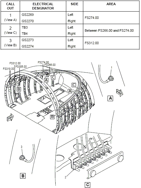
- Locate and inspect Terminal block TB4 for the right, make sure that the electrical connections at window terminals T4 is properly torqued.
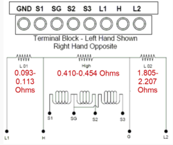
- Check the resistance value of the 3 temp sensors in the respective windshield. The key to this step is all 3 should be relatively the same. The outside air temp would be a factor. The tech could compare resistance readings to that of the known good windshield on the other side of the plane.
Nominal resistance values could be:
Terminals 65°F 80°F S1-SG 307 Ω ±7 Ω 318 Ω ±5 Ω S2-SG 307 Ω ±7 Ω 318 Ω ±5 Ω S3-SG 307 Ω ±7 Ω 318 Ω ±5 Ω Minimum and Maximum values to have a L (R) WSHLD HEAT FAIL caution message:
Terminals Open Shorted S1-SG > 500 Ω < 225 Ω S1-SG > 500 Ω < 225 Ω S1-SG > 500 Ω < 225 Ω NOTE: An Overheat condition (> 180°F) could cause a L (R) WSHLD HEAT FAIL caution message (i.e. Long exposure to the sun):
- R > 400 Ω (180°F) for any valid sensor (Not open or short).
- Compare the Temp Sensors resistance values to the known good Temp Sensors resistance values of the windshield on the Left side
- If a sensor reads outside the nominal values without being OPEN/SHORT, or if a variation of resistance is noticed for the same temperature refer to IS Modsum IS100-30-0002/02/03/05 and AW300-30-0418. An OPEN/SHORT sensor will be rejected by the controller and the system will continue to be serviceable.
- If resistance values are within range, continue with next step.
- If the fault is intermittent the methods below will help reproducing the fault:
- While respecting the pressurization safety precaution, pressurize the aircraft by step of 1 psi. Measure the resistance of the sensors at each step to confirm if all the sensors are within the nominal values.
- Freeze the sensors by applying ice in the sensor area and compare the resistance of the 3 sensors. Repeat the reading while applying heat (the heat of the hand can be sufficient) and confirm if the sensors stay inside nominal values
- If the resistance reading are not nominal and issue is intermittent check connector P172 (Floor disconnect STN 300RHS)
- Inspect Secondary Power Center (A38) Relay (K64) and Time Delay Thermal Detector 70 Amp Relay (K106) for signs of overheat
- If troubleshooting is not conclusive, interrogate the MDC as follow:
- On the cursor control panel, ensure the toggle switch is to the right and select Anti-Ice. ECS and Fuel buttons simultaneously. The MDC main menu should now be displayed on Display Unit #3
- Using the joystick, select Current Faults (if the fault is active) or Aircraft History to research stored faults. From Aircraft History you can then select Fault Message History and locate the fault logged.
- Select the MDC fault from the drop down below to provide additional information to assist in troubleshooting.