01/20/25
Message Overview:
| DDG Reference: | 36-20 |
| Pilot Action (QRH): | ENVR 06-11 |
| System Description: | 36-20-00 - Indicating System 30-12-00 - Wing Anti-Ice System |
| Schematic Diagram: | 36-21-00 - Bleed-Air Leak-Detection System TRIM AIR SCHEMATIC |
| Wiring Diagram: | 36-21-11 - Pack Loop |
Message Description:
The amber 'TRIM AIR LOOP FAIL' (Caution) CAS message indicates the bleed leak detection loops around the trim air ducting have failed. This is only checked during the power-up self-test.
- The IASC #2 has detected problems with both bleed air leak loops around trim air ducting. Through ARINC bus to the DCU the EICAS has displayed the amber 'TRIM AIR LOOP FAIL' message.
Possible Causes:
- Trim Air Loops (MT61, MT36, MT69, MT124)
- Loop Routing Interference
- Trim Air Loop Connectors
Troubleshooting Tips:
Advisory Wire/Service Bulletin:
- AW300-36-0310 - Bleed Loop Connector Cleaning Tool
- AW300-30-0354 - Potential Piccolo Tube Damage When Replacing a Bleed Loop Element
Full Throttle Blog/Forum Articles/Infoservice/Newsletter: None
Flight Operation Notifications Manual (FONM): None
NOTES:
Abbreviation Guide:
| ACS | Air Conditioning System |
| AIPS | Airframe Ice Protection System |
| APU | Auxiliary Power Unit |
| ATS | Air Turbine Starter |
| CBIT | Continuous Built-In-Test |
| CBW | Wing Cross-Bleed Valve |
| CH | Channel |
| Element | Hot Air Leak Detection Sensor with a connector on each end |
| F.S. | Fuselage Station |
| FCV | Flow Control Valve |
| HARSOV | Hot Air Regulating and Shut-off Valve |
| HPGC | High Pressure Ground Connection |
| HPV | High Pressure Valve |
| IASC | Integrated Air System Controller |
| IBIT | Initiated Built-In-Test |
| IPV | Intermediate Pressure Valve |
| Loop | Assembly of several elements connected together in series to detect Hot air leaks in a given system |
| MDC | Maintenance Diagnostic Computer |
| PBIT | Power Up Built-In-Test |
| PCV | Pre-cooler Crossover Valve |
| TCV | Temperature Control Valve |
| WAIV | Wing Anti-ice Valve |
| W.S. | Wing Station |
Bleed air loops are the detection element used to indicate that a leak has occurred in the bleed air system.
- The ducting has a insulation cover that will contain the air leaking from the ducting routing it to a insulation vent hole.
- The loop elements are electrically connected in series and the concentric outer conductor is connected to the aircraft ground. The layer of eutectic salt compound insulates the outer conductor from the inner conductor. When hot bleed-air gets on the loop element, the eutectic salt compound becomes conductive and lets the outer conductor make contact with the inner conductor. The IAS controller senses that the outer conductor is grounded and supplies the inner conductor with alternating current for its resistance measurement. The IAS controller measures this resistance and shows the correct message on the EICAS.
- The intermediate pressure system loop element senses a bleed-air leak when the temperature is more than 255°F (123.90°C).

Quick Links:
| Standard Aircraft Configuration for Maintenance | AMM 12-00-00-867-803 |
| Electrical/Electronic Safety Precautions | AMM 24-00-00-910-801 |
| Electrostatic-Discharge Safety Precautions | AMM 24-00-00-910-802 |
| Connect Electrical Power to the Aircraft | AMM 24-00-00-861-801 |
| Remove the Electrical Power from the Aircraft | AMM 24-00-00-861-802 |
| Component Location | AMM 36-21-00-992-801 |
| Operational Test of the Bleed-Air Leak-Detection and Warning System | AMM 36-21-00-710-801 |
| Initiation Test of the Bleed-Air Leak-Detection Loops | AMM 36-21-00-740-801 |
| Resistance Check of the Bleed-Air Leak-Detection Loops | AMM 36-21-00-760-801 |
| Removal of the Trim-Air-Supply Leak-Detection Element | AMM 36-21-09-000-801 |
| Installation of the Trim-Air-Supply Leak-Detection Element | AMM 36-21-09-400-801 |
| Removal of the Aft Trim-Air Leak-Detection-Element | AMM 36-21-09-000-802 |
| Installation of the Aft Trim-Air Leak-Detection-Element | AMM 36-21-09-400-802 |
| Removal of the Forward Trim-Air Leak-Detection-Element | AMM 36-21-09-000-803 |
| Installation of the Forward Trim-Air Leak-Detection-Element | AMM 36-21-09-400-803 |
| Removal of the Baggage-Compartment Leak-Detection Element | AMM 36-21-09-000-804 |
| Installation of the Baggage-Compartment Leak-Detection Element | AMM 36-21-09-400-804 |
Troubleshooting Recommendations:
- If no fault is shown or the system is intermittent, do the following steps:
- Go into the LRU Index/Operations and select IASC #2 channel B to display the IASC Channel B menu. Select Leak Detection Test. The test page will provide pages to perform a leak detection system test and check past event locations. The test will check all of the loops the IASC is monitoring and pass or fail them. This test may fail if there is a lot of action going on in the IASC, retesting may pass the failed loops. This test is disabled with the wing heat system on. Perform the test of the bleed air leak detection loops IAW AMM 36-21-00-710-801.
- The test will identify if the respective loop has a short or open.Perform the initiation (IBIT) test of the bleed air leak detection loops IAWAMM 36-21-00-740-801.
- If a loop fails, or a fault has been logged into the MDC, use the steps below to further isolate the condition.
- Interrogate the MDC as follows:
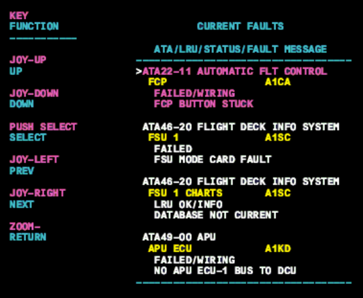
- On the cursor control panel, ensure the toggle switch is to the right and select Anti-Ice, ECS and Fuel buttons simultaneously. The MDC main menu should now be displayed on Display Unit #3.
- Using the joystick, select Current Faults (if the fault is active) or Aircraft History to research stored faults. From Aircraft History you can then select Fault Message History and locate the fault. Going into advanced diagnostics will provide an equation id for the fault identified.
- Select the MDC fault or equation from the drop down below to provide additional information to assist in troubleshooting.
NOTE: Before replacing a loop always look at the loop for routing, ensure loop is not too close to the plumbing or the bleed hole on a valve. Review AMM 36-21-00-992-801 for component location. See individual loops for specific routing information. - Use a Tegam meter to check capacitance and inductance between the inner and outer conductor of the corresponding loop. Perform the impedance check per the Leak Detection How To.
- Trim Air loop Information
- Trim Air Loop schematic
- The test will identify if the trim loop has a short or open. MT61, MT36, MT69, MT124 (#2 IASC monitored loop).
- If the Trim Air Leak Detection loops do not meet resistance checks then replace the affected LDE.
LOOP Triggering Value (OHMS) Trim Air Loops 62Ω