08/25/22
Message Overview:
Message Description:
The cyan 'BLEED LOOP FAULT' CAS advisory message posts when one of the bleed leak detection element loops has detected a fault. Typical faults are an open circuit or a short circuit.
The cyan 'BLEED LOOP FAULT' message will also post when one loop in a dual loop system has detected an overheat condition for more than five minutes and the other loop has not. The overheat applies to the right wing system, left wing system and the pack system as these are the only dual loop systems.
NOTE: If both loops detect an overheat condition, a red message will post for the respective circuit.


Possible Causes:
- Leading Edge Upper Fire Loop
- Leading Edge Lower Fire Loop
- Connectors
Troubleshooting Tips:
Advisory Wire/Service Bulletin:
- AW300-36-0008 - "WING ANTI-ICE LEAK" EICAS Message During Climb
- AW300-36-0310 - Bleed Loop Connector Cleaning Tool
- AW300-30-0354 - Potential Piccolo Tube Damage When Replacing a Bleed Loop Element
- AW300-36-0387 - Bleed Air Leak Detection Loop
Forum Articles/Infoservice/Newsletter: None
Troubleshooting Guide for Bleed Loops
NOTE: If the bleed loop resistance value is within limits, try cleaning the bleed loop connections per AMM 51-25-00-110-801 and then reapply lubrication to the connections per WM 20-20-00. Lubrication part number is called out in each bleed loop installation procedure. Run the aircraft after the cleaning and applying lubing procedure and see if the BLEED LOOP FAULT clears.
Quick Links:
| Operational Test of the Bleed-Air Leak-Detection and Warning System | AMM 36-21-00-710-801 |
| Wiring - Maintenance Practices - ALL | SPM 20-12-00-02 |
| Wire Repair - Maintenance Practices - ALL | SPM 20-12-10-02 |
| Electrical Connectors - Maintenance Practice - ALL | SPM 20-20-00-02 |
Troubleshooting Recommendations:
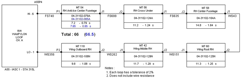
- Gain access to IASC #1 through the LH aft nose kidney panel 141BL or gain access to the IASC #2 which is underneath and outboard of the lavatory sink, just forward of the water pallet.
- Disconnect connector A55P4 (or A56P4) from the IASC and check resistance between the respective pins for the respective resistance listed in the reference documents listed above.
- Isolate a system open circuit through standard practices by isolating the six* different loops and wiring from the IASC. Repair faulty wire segment or replace loop as required.
*Only the first loop is identified, the IASC and MDC cannot identify which section of a multiple loop segment is at fault during a short or open condition and will only list the first loop of the segment. - Left Wing/Fuselage
- Left Wing/Pylon
- Right Wing/Fuselage
- Right Wing/Pylon
- Interrogate the MDC as follows:
- On the cursor control panel, ensure the toggle switch is to the right and select Anti-Ice, ECS and Fuel buttons simultaneously. The MDC main menu should now be displayed on Display Unit #3.
- Using the joystick, select Current Faults (if the fault is active) or Aircraft History to research stored faults. From Aircraft History you can then select Fault Message History and locate the fault. Going into advanced diagnostics will provide an equation id for the fault identified.
- Determine if fault was caused by an open circuit, short circuit or a leak then select fault in drop down menus below:
Open/Short circuit
Leak detected
NOTE: If the resistance is around double the norm, the IASC will post a Circuit Open message. In this case try cleaning the bleed loop connectors starting at the wing outboard position.
NOTE: If the center conductor resistance is around double the norm, the IASC will post a Circuit Open message in the MDC. In this case the problem can usually be isolated to one connector that has built up some surface corrosion between the male/female connection. While checking the resistance, try tapping on the respective connectors starting at the wing outboard position. If the meter remains steady, move to the respective connector at the wing root. If the meter is still steady, try tapping on the respective connector in the aft/outboard of the wheel well. One of these positions is likely where the problem is located.
Usually, it is one of the 4 circuits that monitors the wing anti-ice.
OPEN does not necessarily mean that the circuit is completely open, it just means that the center conductor resistance value is double what it is suppose to be and the only logic written into the IASC is to tell the MDC there is an open.
The technician will need to put a multimeter on pins 1 & 6 for the left wing/pylon circuit (or right wing/pylon circuit) or pins 4 & 5 for the left wing/fuselage circuit (or right wing/fuselage circuit), on the respective IASC connector P4.
The technician will notice the meter is not reading 65 to 68 ohms as it should. The reading may be higher (i.e.107 Ω).
Have a technician watch the meter and while another technician gives the airplane a few love taps with his bare hand at the points illustrated on the below picture. They are numbered according to the probability of being bad.
Typically the meter will become erratic as the other technician is tapping on one of the sweet spots in the picture. When this happens, the technician needs to open the inspection panel. Now the technician can tap directly on the connector. If bad, the meter will become very erratic. Typically, separating the connector from the LDE and cleaning it with contact cleaner will repair the problem.