01/23/25
Message Overview:
| DDG Reference: | 36-20-1 |
| Pilot Action (QRH): | ICE 12-1 |
| System Description: | 30-12-00 - Wing Anti-Ice System 36-20-00 - Indicating System |
| Schematic Diagram: | SSM 36-21-00-101 - Bleed-Air Leak-Detection System L WING A/ICE LOOP SCHEMATIC R WING A/ICE LOOP SCHEMATIC |
| Wiring Diagram: | WM 36-21-13-1_001 - Sheet 1 - Left Anti-Ice Fuselage Loop - ALL WM 36-21-15-1_001 - Sheet 1 - Right Anti-Ice Fuselage Loop - ALL |
Message Description:
A red 'WING ANTI-ICE LEAK' (Warning) Crew Alerting System (CAS) message indicates the high pressure bleed air used to heat the Wing Leading Edge is misdirected and blowing aft onto the wing forward spar or the sensors are incorrectly positioned.
NOTE: The WING ANTI-ICE LEAK bleed loops are a Dual Loop System. Both loops need to detect the overheat in order to display the WING ANTI-ICE LEAK (Warning) CAS message.
NOTE: If one of the two loops was detected failed during the Power-up Built-In Test (PBIT), the controller will display the WING ANTI-ICE LEAK (Warning) CAS message if the remaining good loop detects an overheat condition without the second loop confirmation.
Possible Causes:
- Left Bleed Loop Sensor 1 (MT67)
- Right Bleed Loop Sensor 1 (MT38)
- Right Bleed Loop Sensor 2 (MT40)
- Right Bleed Loop Sensor 3 (MT71)
- Left Inboard Temperature Sensor (MT41)
- Right Inboard Temperature Sensor (MT32)
- Left Outboard Temperature Sensor (MT43)
- Right Outboard Temperature Sensor (MT34)
- Dirty Wing Tip Connector
- Integrated Air System Controller 1 (IASC) (A55)
- Integrated Air System Controller 2 (IASC) (A56)
- Data Concentrator Unit (DCU) (A14)
- Associated Wiring
Troubleshooting Tips:
Advisory Wire/Service Bulletin:
- AW300-36-0008 - "WING ANTI-ICE LEAK" EICAS Message During Climb
- AW300-36-0310 - Bleed Loop Connector Cleaning Tool
- AW300-30-0354 - Potential Piccolo Tube Damage When Replacing a Bleed Loop Element
- AW300-36-0387 - Bleed Air Leak Detection Loop Elements
Full Throttle Blog/Forum Articles/Infoservice/Newsletter: None
Flight Operation Notifications Manual (FONM):
- [ Challenger 350 ] FON 01-16 - ICE-001 - [WING, ANTI−ICE LEAK] (Warning/Red) CAS Message During Climb
NOTES:
- Troubleshooting Guide for Bleed Loops
- Upon experiencing a red 'WING ANTI-ICE LEAK' CAS message during climb at maximum power, the AFM R10 Procedure 03-27-01 procedures must be followed. Review AW300-36-0008 procedures must be followed.
- Leak detection sensors monitor the bleed air lines from the pylon and along the leading edge piccolo tubes for unacceptable leaks in the system
- There are two loops along each line, IASC 1 channel B monitors loops RH Pylon/Wing Loop and LH Fuselage/Wing Loop. IASC 2 channel B monitors RH Fuselage/Wing Loop and LH Pylon/Wing Loop
- Each loop element has a concentric outer conductor, a layer of eutectic salt compound and an inner conductor. The loop elements are connected to the IAS controllers through the routing of the usual aircraft harnesses
- The loop elements are electrically connected in series and the concentric outer conductor is connected to the aircraft ground. The layer of eutectic salt compound insulates the outer conductor from the inner conductor. When hot bleed-air gets on the loop element, the eutectic salt compound becomes conductive and lets the outer conductor make contact with the inner conductor. The IAS controller senses that the outer conductor is grounded and supplies the inner conductor with alternating current for its resistance measurement
- The IAS controller measures this resistance and shows the correct message on the EICAS
- If the temperature in the area of the wing anti-ice ducts is more than 460°F (237.80°C), the loop element in that area senses a bleed-air leak
Quick Links:
| Removal of the Integrated Air System (IAS) Controller | AMM 21-31-01-000-801 |
| Installation of the Integrated Air System (IAS) Controller | AMM 21-31-01-400-801 |
| Operational Test of the Integrated Air System (IAS) Controller | AMM 21-31-01-710-801 |
| Operational Test of the Wing Anti-Ice System | AMM 30-10-00-710-801 |
| Removal of the Inboard Leading-Edge Temperature Sensor | AMM 30-11-01-000-801 |
| Installation of the Inboard Leading-Edge Temperature Sensor | AMM 30-11-01-400-801 |
| Removal of the Outboard Leading-Edge Temperature Sensor | AMM 30-11-03-000-801 |
| Installation of the Outboard Leading-Edge Temperature Sensor | AMM 30-11-03-400-801 |
| Removal of the Data Concentrator Unit (DCU) | AMM 31-41-01-000-802 |
| Installation of the Data Concentrator Unit (DCU) | AMM 31-41-01-400-802 |
| Component Location | AMM 36-21-00-992-801 |
| Operational Test of the Bleed-Air Leak-Detection and Warning System | AMM 36-21-00-710-801 |
| Resistance Check of the Bleed-Air Leak-Detection Loops | AMM 36-21-00-760-801 |
| Removal of the Left Bleed-Loop Element | AMM 36-21-01-000-801 |
| Installation of the Left Bleed-Loop Element | AMM 36-21-01-400-801 |
| Removal of the Wing-Root Leak-Detection Element | AMM 36-21-17-000-801 |
| Installation of the Wing-Root Leak-Detection Element | AMM 36-21-17-400-801 |
| Removal of the Wing-Middle Leak-Detection Element | AMM 36-21-17-000-802 |
| Installation of the Wing-Middle Leak-Detection Element | AMM 36-21-17-400-802 |
| Removal of the Wing-Outboard Leak-Detection Element | AMM 36-21-17-000-803 |
| Installation of the Wing-Outboard Leak-Detection Element | AMM 36-21-17-400-803 |
| Safety Precautions - Maintenance Practices - ALL | SPM 20-00-01-02 |
| Wire Repair - Maintenance Practices - ALL | SPM 20-12-10-02 |
| Electrical Connectors - Description and Operation - ALL | SPM 20-20-00-00 |
Troubleshooting Recommendations:
WARNING: DO NOT USE A METER THAT APPLIES DC VOLTAGE. DO NOT USE INSULATION RESISTANCE "MEGGER" TESTERS OR DIELECTRIC VOLTAGE "HYPOT" TESTERS. THESE WILL DAMAGE THE SENSING ELEMENT (Ref. CMM 26-14-47).
- Upon experiencing a red 'WING ANTI-ICE LEAK' CAS message during climb at maximum power, the AFM R10 Procedure 03-27-01 procedures must be followed. Review AW300-36-0008 for additional details on this condition.
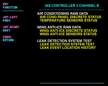
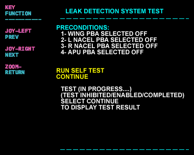
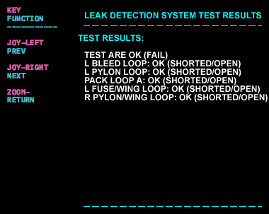
- Go into the system diagnostics to the IASC 2 channel B to display the IASC Channel B menu. The IASC LRU test page will provide pages to perform a leak detection system test and check past event locations.
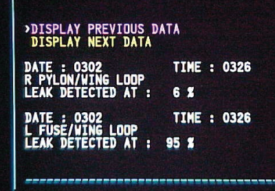
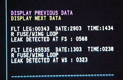
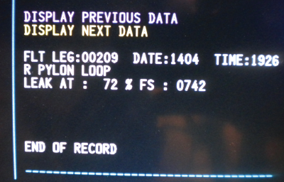
Leak Event Location History
The Leak Event Location History will identify when the system posted a fault, what loop failed and a general location based on.
The percentage location starts at the wing tip being 0, tailcone section 100, so a 5% indication will be 5% of the total loop length from the wing tip inboard.
- An approximate fuselage/wing station location of the overheat condition
- A percentage and fuselage/wing station
WING ANTI-ICE LEAK (B3-007866)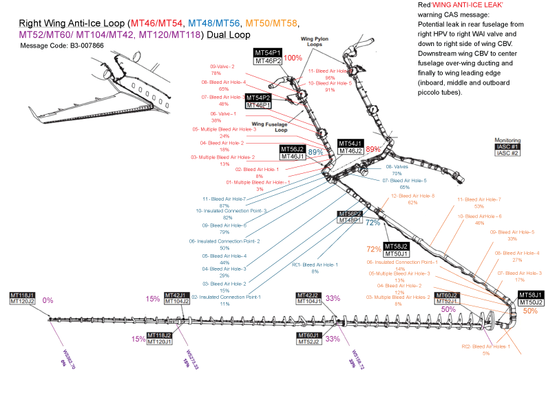
WING ANTI-ICE LEAK (B3-007144)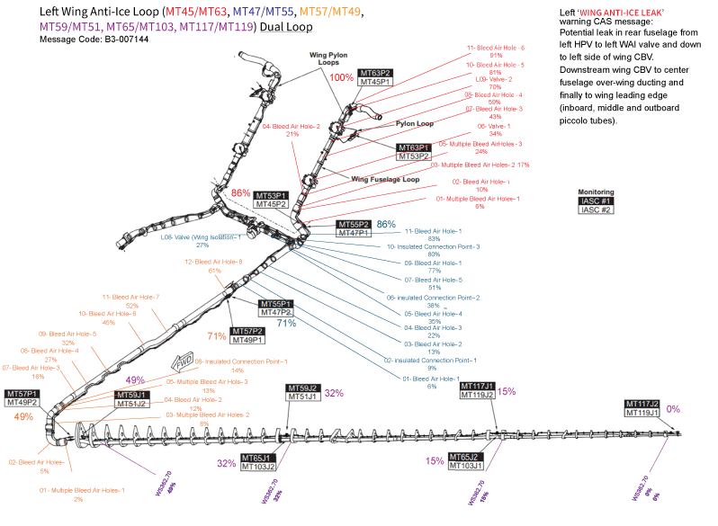
- When a location is identified in the leak event location history, inspect with a borescope the plumbing for possible leaks.
- Perform the operational test of the bleed air leak detection loops IAW AMM 36-21-00-710-801. The test will identify if the wing loop has a short or open (>132 Ω). Check for shorts or open conditions referencing and AMM Resistance Check of the Bleed-Air-Leak Detection Loops AMM 36-21-00-760-801. Perform the impedance check per the Leak Detection How To.
NOTE: Cleaning Wing Tip Connectors can bring loop resistance back down to normal. - If the leak cannot be identified, perform the wing anti-ice system operational check IAW AMM 30-10-00-710-801. This test will check all of the loops the IASC is monitoring and pass or fail them. This test may fail if there is a lot of action going on in the IASC, retesting may pass the failed loops. This test is disabled with the wing heat system on.
NOTE: Before replacing a loop always look at the loop for routing, ensure loop is not too close to the plumbing or a valve. Review AMM 36-21-00-992-801 for component location. See individual loops for specific routing information. - Select the associated MDC Fault message:
- Do close out.