

10/22/25
Message Overview:
Message Name:
DIN09A REASONABLENESS
Message Code:
B3-230146
Associated CAS:
| Reporting LRU: | PSEU LRU |
| System Description: | 32-60-00 - Position and Warning |
| Schematic Diagram: | 32-61-00 - Position and Indication System |
| Wiring Diagram: | 32-31-01 - Landing-Gear Selector Valve 32-61-09 - Proximity Sensor Electronic Unit |
Message Description:
PSEU detects an unreasonableness condition on DIN09A (EXTEND MONITOR2) input.
Possible Causes:
- Landing-Gear Control Handle (S125)
- Landing-Gear Selector Valve (V9)
- Junction Box (JB4)
- Proximity-Sensor Electronic Unit (PSEU) (A9)
- Associated Wiring
Troubleshooting Tips:
Advisory Wire/Service Bulletin: None
Full Throttle Blog/Forum Articles/Infoservice/Newsletter: None
Flight Operation Notifications Manual (FONM): None
Quick Links:
| Standard Aircraft Configuration for Maintenance | AMM 12-00-00-867-803 |
| Electrical/Electronic Safety Precautions | AMM 24-00-00-910-801 |
| Electrostatic-Discharge Safety Precautions | AMM 24-00-00-910-802 |
| Connect Electrical Power to the Aircraft | AMM 24-00-00-861-801 |
| Removal of the Junction Box JB4 | AMM 24-63-13-000-802 |
| Installation of the Junction Box JB4 | AMM 24-63-13-400-802 |
| Operational Test of Junction Box JB4 Card 2 | AMM 24-63-13-710-802 |
| Removal of the Landing-Gear Selector Valve | AMM 32-31-01-000-801 |
| Installation of the Landing-Gear Selector Valve | AMM 32-31-01-400-801 |
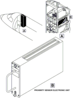
| Removal of the Proximity-Sensor Electronic Unit (PSEU) | AMM 32-61-09-000-801 |
| Installation of the Proximity-Sensor Electronic Unit (PSEU) | AMM 32-61-09-400-801 |
| Functional Test of the Proximity-Sensor Electronic Unit (PSEU) | AMM 32-61-09-720-801 |
| Removal of the TAWS/LANDING GEAR Control-Panel | AMM 34-42-09-000-801 |
| Installation of the TAWS/LANDING GEAR Control-Panel | AMM 34-42-09-400-801 |
| Operational Test of the TAWS/LANDING GEAR Control-Panel | AMM 34-42-09-710-801 |
Troubleshooting Recommendations:
- Do wiring check from Gear Control Handle (PL10) connector or Selector Valve and PSEU (A9), is result as expected?
From To Expected Result Result PL10P1 - 1 A9BP1 - 10E Continuity PL10P1 - 1 A9BP1 - 10F Continuity - If YES, continue with next step.
- If NO, repair wiring and do close out.
- Do wiring check from the PSEU (A9) connector and Selector Valve (V9), is result as expected?
From To Expected Result Result A9BP1 - 15A V9P1 - D Continuity PL10P1 - 4 Continuity A9BP1 - 13A V9P1 - E Continuity PL10P1 - 2 Continuity - If YES, continue with next step.
- If NO, repair wiring and do close out.
- Access and disconnect the Landing Gear Selector Valve connector V9P1. Perform a resistance check of the extend and retract solenoids as follows:
From To Result V9P1-A V9P1-B V9P1-D V9P1-E - If both solenoids have the same resistance, continue with next step.
- If the solenoids have different resistance values, replace the Landing Gear Selector Valve and do close out.
- Perform a wiring check from the TAWS/LANDING GEAR Control Panel connector PL10P1 Pin 17 and 18 to the aircraft ground.
- If wiring defects are found, repair defective wiring as required and do close out.
- If no defects are found, continue with next step.
- Replace the TAWS/LANDING GEAR Control Panel PL10. Is the fault still present?
- If YES, continue with next step.
- If NO, do close out.
- If possible, download and have field service review the PSEU NVM. Further troubleshooting will depend on results of the PSEU NVM.
- If the wiring checks good and the NVM does not identify external inputs as the fault, replace the PSEU.
