

01/22/25
Message Overview:
Message Name:
R BLEED DUCT AIR LEAK
Message Code:
B3-007685
| Reporting LRU: | Right Bleed Duct |
| Associated CAS: | R BLEED LEAK (Warning) |
| System Description: | 36-00-00 - Pneumatic System |
| Schematic Diagram: | SSM 36-21-00-101 - Bleed-Air Leak-Detection System |
| Wiring Diagram: | WM 36-21-11-1_001 - Sheet 1 - Pack Loop - ALL |
Message Description:
An hot air leak has been detected in the RIGHT BLEED DUCTING running from the Right Bleed Valve to the Cross Bleed Valve and the Right Flow Control Valve.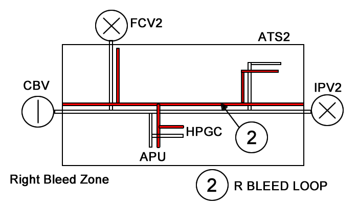
Possible Causes:
- Right Bleed Duct
- Right Bleed Valve
- Cross Bleed Valve
- Right Control Valve
- Right (R) Bleed Loop Sensor 1 (MT38)
- Right (R) Bleed Loop Sensor 2 (MT40)
- Right (R) Bleed Loop Sensor 3 (MT71)
- Right (R) Bleed Loop Routing
- Associated Wiring
Troubleshooting Tips:
Advisory Wire/Service Bulletin: None
Full Throttle Blog/Forum Articles/Infoservice/Newsletter: None
- Forum Article May 2013 - Challenger 300: Routing of the Bleed Air Detection Element on the Intermediate Pressure Valve - ATA 36-21
Flight Operation Notifications Manual (FONM): None
Fault Confirmation Procedure:
- Message# = 1
- Comp Id =.
- {Term Definitions}
- IAS2A-30 XX 351 11 EXCT XXXX-XXXX XXXX-XXXX XXXX-XTXX 351B: 11; RIGHT BLEED LEAK DETECT
NOTES:
Quick Links:
| Removal of the Flow Control Valve | AMM 21-51-09-000-801 |
| Installation of the Flow Control Valve | AMM 21-51-09-400-801 |
| Removal of the Wing Cross-Bleed Valve | AMM 30-11-05-000-801 |
| Installation of the Wing Cross-Bleed Valve | AMM 30-11-05-400-801 |
| Removal of the Lower Bleed Duct | AMM 36-11-41-000-801 |
| Installation of the Lower Bleed Duct | AMM 36-11-41-400-801 |
| Removal of the Upper Bleed Duct | AMM 36-11-43-000-801 |
| Installation of the Upper Bleed Duct | AMM 36-11-43-400-801 |
| Component Location | AMM 36-21-00-992-801 |
| Operational Test of the Bleed-Air Leak-Detection and Warning System | AMM 36-21-00-710-801 |
| Initiation Test of the Bleed-Air Leak-Detection Loops | AMM 36-21-00-740-801 |
| Resistance Check of the Bleed-Air Leak-Detection Loops | AMM 36-21-00-760-801 |
| Fenwal Safety Systems | CMM 26-14-47 |
| Safety Precautions - Maintenance Practices - ALL | SPM 20-00-01-02 |
| Wiring - Maintenance Practices - ALL | SPM 20-12-00-02 |
| Wire Repair - Maintenance Practices - ALL | SPM 20-12-10-02 |
Troubleshooting Recommendations:
- Locate the short circuit or leak using the Leak Event location function.
- Check for short circuit at the corresponding connector.
NOTE: Before replacing a loop always look at the loop for routing, ensure loop is not too close to the plumbing or the bleed hole on a valve. Review AMM 36-21-00-992-801 for component location. See individual loops for specific routing information. - Use a Tegam meter to check capacitance and inductance between the inner and outer conductor of the corresponding loop. Perform the impedance check per the Leak detection how to.
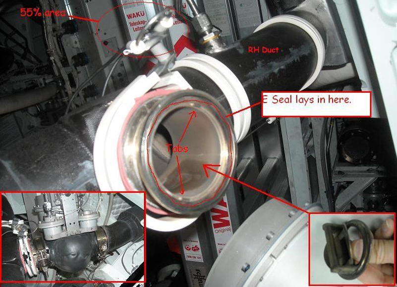
- Ducting inspection is required. Check the e-seal located at the RH IPV.
- Check for short circuit at the corresponding connector.
Leak Event Location History
The Leak Event Location History will identify when the system posted a fault, what loop failed and a general location based on approximate fuselage/wing station and percentage location of the overheat condition.
The CH350 reports the name of the bleed loop and fuselage station or wing station and general location of the leak in percentage. A 0% location starts at the beginning of the loop and the end of the loop is 100% so a 5% indication will be 5% of the total loop length.
R BLEED LEAK
TRIM AIR LEAK
- Once the percentage value is obtained from the MDC, refer to mapping tool representing all potential bleed leak locations in term of percentage, for each metered bleed air hole and LRU connections point. This will help to quickly troubleshoot source of the leak..
- If the leak can not be identified, perform the system functional check IAW AMM 36-21-00-710-801
Leak Detection Test
The test will check all of the loops the IASC is monitoring and pass or fail them. This test may fail if there is a lot of action going on in the IASC, retesting may pass the failed loops. This test is disabled with the wing heat system on. Perform the initiation (IBIT) test of the bleed air leak detection loops IAW AMM 36-21-00-740-801.
RH Bleed loop information
RH Bleed loop schematic information
The test will identify if the respective loop has a short or open (>75 Ω) MT38, MT40 or MT 71 (RH system loop). Perform resistance checks on the applicable loop per AMM 36-21-00-760-801
| LOOP | VALUE (OHMS) |
|---|---|
| LH and RH Bleed | 75 Ω |