

03/26/25
Message Overview:
Message Name:
FAULTY FUEL INDICATION
| Message Code: | 284OBS001 |
| Effectivity: | AIRCRAFT 20501 - 20999 |
| System: | Fuel |
| Associated CAS: | None |
| System Description: | 28-23-00 - Refuel/Defuel System 28-40-00 - Indicating |
| Schematic Diagram: | SSM 28-41-00-101 - Fuel Management and Quantity Gauging System (FMQGS) |
| Wiring Diagram: | WM 28-41-13-1_001 - Sheet 1 - Fuel Quantity Probes (LHS) - ALL WM 28-41-15-1_001 - Sheet 1 - Fuel Quantity Probes (RHS) - ALL |
Message Description:
The fuel quantity or temperature indication on the fuel synoptic page is erroneous or missing.
NOTE: The Fuel Quantity Computer (A57) processes fuel gauge and fuel level sensor signals to provide fuel quantity, temperature status and warning and failure condition information that is stored in a nonvolatile memory.
- After computation, the Fuel Quantity and Gauging Computer (FQGC) sent the fuel quantity information on ARINC 429 link to the Remote Data Concentrator (RDC), the RDC in turn sends this to the Data Concentrator Unit (DCU) for display on Engine Indicating and Crew Alerting System (EICAS).


Possible Causes:
- Fuel Probe
- Fuel System Computer Unit (A57)
- Associated Wiring
Troubleshooting Tips:
Advisory Wire/Service Bulletin:
- AW300-28-0118 - No Fault Found Initiative: Fuel Quantity and Gauging Computer (FQGC)
- AW300-28-0138 - Fuel Tank Sumping
- AW300-28-0398 - SmartFix Plus Fuel System Troubleshooting Updates
Full Throttle Blog/Forum Articles/Infoservice/Newsletter: None
Flight Operation Notifications Manual (FONM): None
NOTES:
- Because water has a higher dielectric constant than fuel, water in fuel tanks will affect the reading of fuel quantity probes if it comes in contact with them. The reading will become out of range and the FQGC will stop sending fuel quantity for that tank (magenta dashes). At a certain point, enough water in a fuel quantity probe will 'short' the probe's concentric tubes and collapse the oscillator signal feeding all probes for that tank. The FQGC will identify the oscillator as faulty and will shut down the affected tank channel and identify the fault as internal to the FQGC (MDC code B3-006789).
- Before replacing the FQGC, make sure the failure is not caused by the presence of water contamination on fuel probes.
- When sumping water from affected fuel tank it is preferable to have fuel probes immersed in fuel, in order for the water to pool at the bottom of the fuel tank.
- To get most of the water to the bottom of the tank, for T/S purposes do not move aircraft for at least 2 hours before sumping.
- You can view and compare the Left wing and Right wing Fuel probe capacitance values via the MDC on the Fuel Probe Capacitance Display page. If one probe seems off compared to the other side, the affected probe may need to be cleaned.
- Fill the Detailed FQGC Troubleshooting Report if Fuel Quantity Gauging Computer (FQGC) pn 738360-1-2 is replaced.
Quick Links:
| Standard Aircraft Configuration for Maintenance | AMM 12-00-00-867-803 |
| Use of Fuel Biocide Additive When Pressure Refueling | AMM 12-11-01-620-801 |
| Pressure Refueling | AMM 12-11-01-650-801 |
| Use of Fuel Anti-Icing Additive When Pressure Refueling | AMM 12-11-01-660-801 |
| Suction Defueling | AMM 12-11-09-650-801 |
| Use of Fuel Biocide Additive When Gravity Refueling | AMM 12-11-13-620-801 |
| Gravity Refueling | AMM 12-11-13-650-801 |
| Use of Fuel Anti-Icing Additive When Gravity Refueling | AMM 12-11-13-660-801 |
| Microbial Growth Test | AMM 12-11-28-280-801 |
| Fuel-System Safety Precautions | AMM 28-00-00-910-801 |
| Cleaning of the Fuel Tank | AMM 28-10-00-160-801 |
| Biocide Treatment of the Fuel Tank | AMM 28-10-00-620-801 |
| Drain Water from the Fuel Tank | AMM 28-10-00-680-801 |
| Prepare Fuel Tank for Access | AMM 28-10-00-840-801 |
| Removal of Fuel Fumes | AMM 28-10-00-840-802 |
| Close the Fuel Tank after Maintenance | AMM 28-10-00-840-803 |
| General Visual Inspection of the Fuel Storage System | AMM 28-10-00-210-801 |
| Operational Check for Water in the Fuel | AMM 28-10-00-750-801 |
| Component Location | AMM 28-11-00-992-801 |
| Component Location | AMM 28-41-00-992-801 |
| Built-In Test of the Fuel-Quantity Gauging System | AMM 28-41-00-740-801 |
| Removal of the Fuel Quantity Computer | AMM 28-41-01-000-801 |
| Installation of the Fuel Quantity Computer | AMM 28-41-01-400-801 |
| Removal of the Fuel Quantity Probe | AMM 28-41-13-000-801 |
| Installation of the Fuel Quantity Probe | AMM 28-41-13-400-801 |
| Removal of the Fuel Quantity Probe with Compensator | AMM 28-41-13-000-802 |
| Installation of the Fuel Quantity Probe with Compensator | AMM 28-41-13-400-802 |
| Capacitance Check of the Fuel Quantity Probes | AMM 28-41-13-760-801 |
| Cleaning of the Fuel Quantity Probes | AMM 28-41-13-160-801 |
| Removal of the Remote Data Concentrator (RDC) | AMM 31-41-05-000-802 |
| Installation of the Remote Data Concentrator (RDC) | AMM 31-41-05-400-802 |
| Removal of the Input/Output Concentrator Unit (IOC) | AMM 31-45-05-000-801 |
| Installation of the Input/Output Concentrator Unit (IOC) | AMM 31-45-05-400-801 |
| Operational Test of the Input/Output Concentrator Unit (IOC) | AMM 31-45-05-710-801 |
| Data Download from the Maintenance Diagnostic Computer (MDC) | AMM 45-45-01-970-802 |
| Safety Precautions - Maintenance Practices - ALL | SPM 20-00-01-02 |
| Wire Repair - Maintenance Practices - ALL | SPM 20-12-10-02 |
| Electrical Connectors - Description and Operation - ALL | SPM 20-20-00-00 |
Troubleshooting Recommendations:
- Review the AWs and NOTEs in the Troubleshooting Tips prior to beginning the troubleshooting.
- Select the active MDC fault or equation from the drop down below prior to following the troubleshooting below.
- If any of the fault codes, listed on that page are present on the aircraft, troubleshoot these fault codes first.
- If none of the fault codes are present, continue with next step.
- Sump at least 2 gallons of fuel from both wing tanks and collector tanks. If water is noticed in a tank, continue sumping until all water is removed.
- Re-rack the Fuel Quantity Gauging Computer (FQGC). Is the fault message still present?
- If YES, go to next step.
- If NO, do close out.
- Access the fuel probe capacitance page on the MFD, check probe values are within the limits below:
- On the CCP L/R select switch to R
- Access the maintenance main menu by pushing the A/ICE, ECS and FUEL buttons simultaneously
- Using the joystick and ENTER button, select the LRU TEST
- Using the joystick and ENTER button, select FQGC
- Using the joystick and ENTER button, select TEST
- Using the joystick and ENTER button, select FUEL PROBES CAPACITANCE DISPLAY
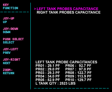
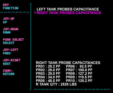
- Note the capacitance values for the respective side fuel probes and note the fuel quantity of each tank as it is displayed on the MDC.
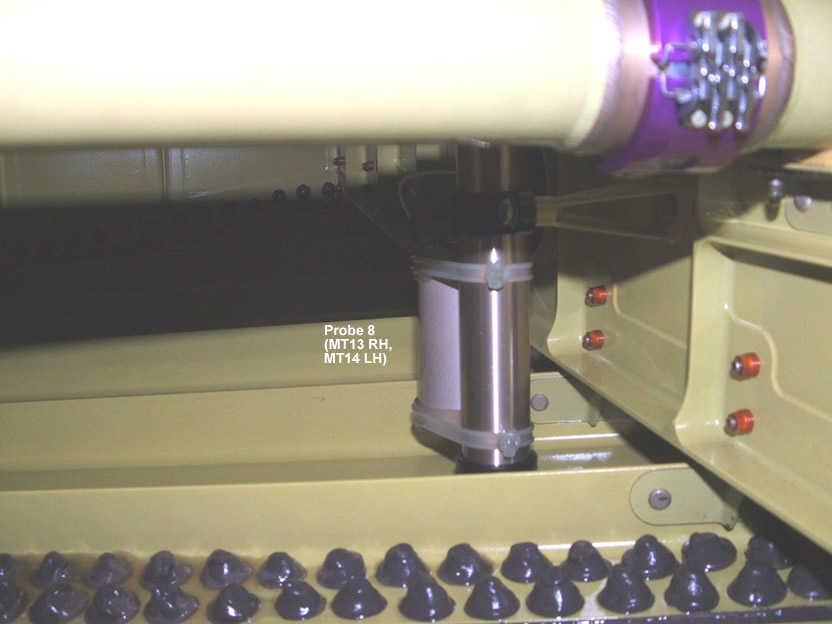
Fuel probe location diagram.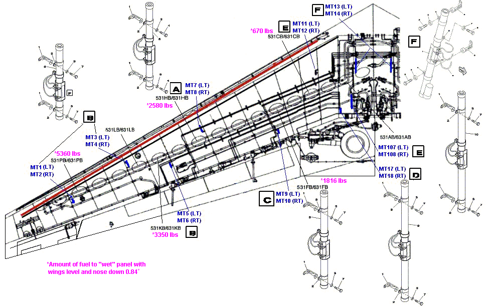
The table below represents estimated pf values with temperatures around 27°C.Probe Designation (odd LH, even RH) pf Dry (new) 0 lbs 2,000 lbs 4,000 lbs 8,000 lbs 10,390 lbs (full) Out of Range Result P1 (MT1/MT2) 28.4 29.1 ±1.5 28.8 28.8 28.8 28.8 <25.88 or >65.1 P2 (MT3/MT4) 28.4 29.1 ±1.5 29 29 29 29 <25.88 or >65.1 P3 (MT5/MT6) 28.4 29.1 ±1.5 28.9 28.9 28.9 33.7 <25.88 or >65.1 P4 (MT7/MT8) 33.3 34.5 ±1.5 33.9 33.9 33.9 52.9 <30.83 or > 77.16 P5 (MT9/MT10) 40 40.8 ±1.5 41.2 42.5 55.4 73.4 <37.13 or >91.93 P6 (MT11/MT12) 62.9 63.7 ±1.5 70.1 79.9 95.7 116.4 <58.66 or >146.01 P7 (MT17/MT18) 58.8 59.7 ±1.5 81.4 98.3 119.6 119.6 <54.8 or >136.2 P8 (MT13/MT14) 78.1 79.1 ±1.5 106.5 123.4 160.1 153.3 <72.94 or >181.43 P9 (MT107/MT108) 62.9 63.7 ±1.5 98 118.5 128.2 128.2 <58.66 or >146.01 P10 64.1* 64.19 ±2* 129.3 129.3 129.4 129.4 <121.39 or >138.42* *Capacitance range values are nominal only when the fuel probe is immersed in fuel.
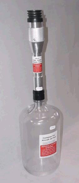
- If the fuel probe capacitance is out of range, there is a possibility of water contamination inside the fuel system, drain water from the fuel tank. A fuel sampler is required to drain the water from the tank.
- If probe readings are still out of tolerance, before replacement attempt to clean the fuel probe. The affected fuel tank may need to be treated with biocide if contamination is found. Refer to AW300-28-0138.
- Replace the Fuel Quantity Gauging Computer (FQGC) (A57).
- Do close out.