04/26/21
Message Overview:
Message Description:
Reported on aircraft POST SB 100-34-36 (Proline 21 Advanced - Option C34-602); While performing AMM task 24-61-25-710-801 essential contactor - adjustment/test (operational test of the electrical system emergency mode), at step (20), The RH MFD and LH MFD were displaying maintenance data and not the normal MFD EICAS and synoptic pages.
Possible Causes:
- Wire CAG5116-22 not caped & stowed at MFD 1 (A29)
- Wire CBH5119-22 not caped & stowed at MFD 2 (A28)
Troubleshooting Tips:
Advisory Wire/Service Bulletin:
- SB 100-34-36 - MODIFICATION - NAVIGATION - INSTALLATION OF THE PRO LINE 21 ADVANCED UPGRADE OPTION (C34-602)
Forum Articles/Infoservice/Newsletter: None
Quick Links:
| Operational Test of the Electrical System Emergency Mode | AMM 24-61-25-710-801 |
| Removal of the Adaptive Flight-Display Unit | AMM 31-61-01-000-801 |
| Installation of the Adaptive Flight-Display Unit | AMM 31-61-01-400-801 |
| Operational Test of the Adaptive Flight-Display Unit | AMM 31-61-01-710-801 |
| Wiring - Maintenance Practices - ALL | SPM 20-12-00-02 |
| Wire Repair - Maintenance Practices - ALL | SPM 20-12-10-02 |
| Electrical Connectors - Maintenance Practice - ALL | SPM 20-20-00-02 |
Troubleshooting Recommendations:
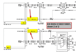
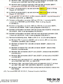
- For Aircraft POST SB 100-34-36 only, access MFD1s rear connector A29P2. Make sure there is no wire connected into pin 42. If wire CG5116-22 is found connected into pin 42, disconnect, cap, and stow as per SB 100-34-36 instructions. Refer to Wiring Diagram K1003110001.
- For Aircraft POST SB 100-34-36 only, access MFD2s rear connector A28P2. Make sure there is no wire connected into pin 42. If wire CG5119-22 is found connected into pin 42, disconnect, cap, and stow as per SB 100-34-36 instructions. Refer to Wiring Diagram K1003110001.
- Perform AMM task 24-61-25-710-801 (essential contactor - adjustment/test (operational test of the electrical system emergency mode).
- Do close out.


Both MFDs displaying maintenance data instead of displaying normal EICAS and Synoptic pages.