

04/26/21
Message Overview:
Message Description:
The amber 'RA' caution flag identifies that the on-side Radio Altimeter is inaccurate or a miscompare between the PFDs exist.
- The system uses a single R/T for radio altimeter indications, left and right indications are sent on left and right data bus to the respective IOC.
- Cross comparator or splits, could be associated with a bad IOC, Radio Altimeter R/T or Data bus failure.
- MDC troubleshooting information may help isolate data validity, prior to component replacement and data bus-ring out.
Possible Causes:
- Radio Altimeter Receiver/Transmitter (RAD ALT) (A32)
- Input/Output Concentrator (IOC) (A4-IOC)
- Data Concentrator Unit (DCU) (A14)
- Associated Wiring
Troubleshooting Tips:
Advisory Wire/Service Bulletin: None
Forum Articles/Infoservice/Newsletter: None
NOTE: A metallic or reflective surface (Water, Ice, metal plates, metal grills, etc...) underneath the RA antennas when aircraft is on the ground can cause erratic readings and cause the unit to fail. The first thing that should be attempted is move the A/C a few feet and test the system again.
Quick Links:
| Removal of the Data Concentrator Unit (DCU) | AMM 31-41-01-000-802 |
| Installation of the Data Concentrator Unit (DCU) | AMM 31-41-01-400-802 |
| Removal of the Input/Output Concentrator Unit (IOC) | AMM 31-45-05-000-801 |
| Installation of the Input/Output Concentrator Unit (IOC) | AMM 31-45-05-400-801 |
| Operational Test of the Input/Output Concentrator Unit (IOC) | AMM 31-45-05-710-801 |
| Operational Test of the Radio Altimeter System | AMM 34-44-00-710-801 |
| Removal of the Radio Altimeter Transceiver | AMM 34-44-01-000-801 |
| Installation of the Radio Altimeter Transceiver | AMM 34-44-01-400-801 |
| Removal of the Radio Altimeter Antenna | AMM 34-44-09-000-801 |
| Installation of the Radio Altimeter Antenna | AMM 34-44-09-400-801 |
| Wiring - Maintenance Practices - ALL | SPM 20-12-00-02 |
| Wire Repair - Maintenance Practices - ALL | SPM 20-12-10-02 |
| Electrical Connectors - Maintenance Practice - ALL | SPM 20-20-00-02 |
Troubleshooting Recommendations:
- Troubleshooting using the MDC current fault page may help isolate the system, verify that power is available and check the data bus information.
- Interrogate the MDC as follows:
- On the cursor control panel, ensure the toggle switch is to the right and select Anti-Ice, ECS and Fuel buttons simultaneously. The MDC main menu should now be displayed on Display Unit #3.
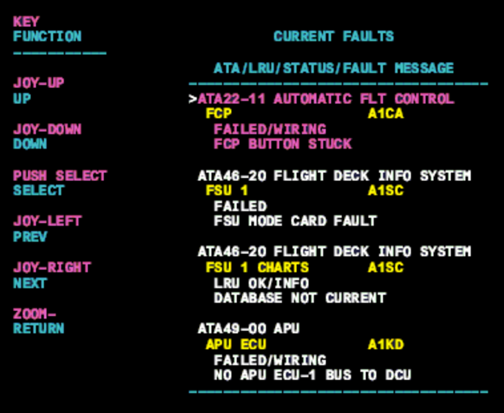
- Using the joystick, select Current Faults (if the fault is active) or Aircraft History to research stored faults. From Aircraft History you can then select Fault Message History and locate the fault. Going into advanced diagnostics will provide an equation id for the fault identified
- Select the MDC fault or equation from the drop down below to provide additional information to assist in troubleshooting.
- If no MDC Fault Codes/Messages are present continue with next step for troubleshooting.
- Swap IOC.
- If squawk remains return IOCs to original positions.
- Continue with next step.
- Replaced Radio Altimeter (RA). Does amber box 'RA' flag clear?
- If YES, do close out.
- If NO, check associated wiring.
- Do close out.