02/19/24
Message Overview:
| DDG Reference: | 30-10-06 |
| Pilot Action (QRH): | ICE 12-15 |
| System Description: | 30-21-00 - Engine Nacelle Anti-Ice System |
| Schematic Diagram: | SSM 75-10-00-101 - Engine Anti-Icing |
| Wiring Diagram: | WM 75-10-01-1_001 - Sheet 1 - Engine Nacelle Anti-Ice (LHS) - ALL |
Message Description:
The cyan 'L ENG A/ICE FAIL ON' advisory CAS Message indicates the respective Nacelle Anti-Ice has failed on.
- The Engine Electronic Control Unit (ECU) has determined that system command compared to system pressure indication for the respective Nacelle is showing pressure in an off condition and has posted the message.
- If the T2 probe Heater has failed on, an amber 'T2' icon will be displayed on the anti-ice synoptic if Engine Anti-Ice bleed air has failed on, a green flow line will be displayed down stream of the failed Anti-Ice Valve on the synoptic.
Possible Causes:
- Left Full Authority Digital Engine Control Channel A (L FADEC A) System (A41)
- Left Full Authority Digital Engine Control Channel B (L FADEC B) System (A43)
- Left Nacelle Anti-Ice Solenoid (V01)
- T2 Probe Heater
Troubleshooting Tips:
Advisory Wire/Service Bulletin:
- AW300-30-0400 - Thermal Anti-Ice Valve (TAIV)
- Honeywell SIL D202208002772 - AS907 Engine Thermal Anti-Ice Valve (TAIV) PN WBG3020G103-003
Forum Articles/Infoservice/Newsletter: None
Quick Links:
| Anti-Ice System - Component Location | AMM 30-11-00-992-801 |
| Removal of the Anti-Ice Control Panel | AMM 30-11-09-000-801 |
| Installation of the Anti-Ice Control Panel | AMM 30-11-09-400-801 |
| Engine Nacelle Anti-Ice - Component Location | AMM 30-21-00-992-801 |
| Operational Test of the Nacelle Anti-Ice System | AMM 30-21-00-710-801 |
| Leak Test of the Nacelle Anti-Ice System | AMM 30-21-00-790-801 |
| Removal of the Cowl Anti-Ice Valve | AMM 30-21-01-000-801 |
| Installation of the Cowl Anti-Ice Valve | AMM 30-21-01-400-801 |
| Removal of the Anti-Ice Dual Pressure Switch | AMM 30-21-03-000-801 |
| Installation of the Anti-Ice Dual Pressure Switch | AMM 30-21-03-400-801 |
| Removal of the Anti-Ice Tubes | AMM 30-21-05-000-801 |
| Installation of the Anti-Ice Tubes | AMM 30-21-05-400-801 |
| Removal of the Engine Electronic Control Unit (ECU) | AMM 76-10-05-000-801 |
| Installation of the Engine Electronic Control Unit (ECU) | AMM 76-10-05-400-801 |
| Wiring - Maintenance Practices - ALL | SPM 20-12-00-02 |
| Wire Repair - Maintenance Practices - ALL | SPM 20-12-10-02 |
| Electrical Connectors - Maintenance Practice - ALL | SPM 20-20-00-02 |
Troubleshooting Recommendations:
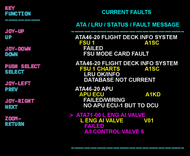
- Interrogate the MDC as follows:
- On the cursor control panel, ensure the toggle switch is to the right and select Anti-Ice, ECS and Fuel buttons simultaneously. The MDC main menu should now be displayed on Display Unit 3.
- Using the joystick, select Current Faults (if the fault is active) or Aircraft History to research stored faults. From Aircraft History you can then select Fault Message History and locate the air condition fault logged.
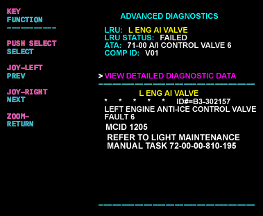
- Select the MDC fault from the drop down below to provide additional information to assist in troubleshooting:
- Do close out.