05/17/22
Message Overview:
| DDG Reference: | 21-61 36-10 |
| Pilot Action (QRH): | ENVR 06-6 |
| System Description: | 36-10-00 - Distribution System |
| Schematic Diagram: | 21-51-00-101 - Filtering and Flow Control System 21-52-00-101 - Air Conditioning system 21-61-00-101 - Temperature Control and Indication 31-41-00-101 - Engine Indication and Crew Alerting System (EICAS) 31-41-00-102 - Engine Indication and Crew Alerting System (EICAS) 36-11-00-101 - Intermediate-Pressure Bleed-Air System |
| Wiring Diagram: | 21-51-03 - Differential Pressure Sensor - ALL 21-51-09 - Flow Control Valve - ALL 21-61-29 - Hot Air Temperature-Sensor - ALL 26-11-01 - Fire-Detection-and-Extinguishing (FIREX) Control-Unit - ALL 31-41-03 - Data Concentrator Unit (Interface) - ALL 36-11-03 - Bleed Pressure Transducer - ALL |
Message Description:
The amber 'R BLEED FAIL' caution CAS message indicates the intermediate pressure valve has failed, (Flow Control Valve).
- The IACS has detected the FCV is failed in the closed position, failed in the open position, or a drift in pressure control settings (pressure is controlled too high, or too low). IASC1 controls the FCV1, IASC2 controls the FCV2.
- If the bleed pressure is above 60 psi, the fail message is posted and the affected bleed pressure display turns amber.
Possible Causes:
- Hot Air Temperature Sensor (HATS) (MT27)
- AIR CONDITIONING / BLEED CONTROL PANEL (PL17)
- R BLEED Push Button Assembly (PBA) (SDS14)
- Integrated Air System Controller 1 (IASC 1) (A55)
- Integrated Air System Controller 2 (IASC 2) (A56)
- Junction Box
- Data Concentrator Unit (DCU) (A14)
- Bleed Pressure Transducer
- Fire-Detection-and-Extinguishing (FIREX) Control Unit (A91)
- R Differential Pressure Sensor
- Associated Wiring
Troubleshooting Tips:
Advisory Wire/Service Bulletin:
- AW300-30-0354 - Potential Piccolo Tube Damage When Replacing a Bleed Loop Element
Forum Articles/Infoservice/Newsletter: None
NOTE: If fault is intermittent or can not be duplicated on the ground, download IASC NVM along with MDC Flight History file and the Service Message History file and send to the CRC.
Quick Links:
| Standard Aircraft Configuration for Maintenance | AMM 12-00-00-867-803 |
| Removal of the Integrated Air System (IAS) Controller | AMM 21-31-01-000-801 |
| Installation of the Integrated Air System (IAS) Controller | AMM 21-31-01-400-801 |
| Operational Test of the Integrated Air System (IAS) Controller | AMM 21-31-01-710-801 |
| Component Location | AMM 21-51-00-992-801 |
| Operational Test of the Filtering and Flow Control System | AMM 21-51-00-710-801 |
| Removal of the Differential Pressure Sensor | AMM 21-51-03-000-801 |
| Installation of the Differential Pressure Sensor | AMM 21-51-03-400-801 |
| Operational Test of the Differential Pressure Sensor | AMM 21-51-03-710-801 |
| Component Location | AMM 21-52-00-992-801 |
| Electrical/Electronic Safety Precautions | AMM 24-00-00-910-801 |
| Electrostatic-Discharge Safety Precautions | AMM 24-00-00-910-802 |
| Connect Electrical Power to the Aircraft | AMM 24-00-00-861-801 |
| Component Location | AMM 24-31-00-992-801 |
| Component Location | AMM 26-11-00-992-801 |
| Operational Test of the Fire-Detection-and-Extinguishing (FIREX) System | AMM 26-11-00-710-801 |
| Removal of the Fire-Detection-and-Extinguishing (FIREX) Control-Unit | AMM 26-11-01-000-801 |
| Installation of the Fire-Detection-and-Extinguishing (FIREX) Control-Unit | AMM 26-11-01-400-801 |
| Removal of the Data Concentrator Unit (DCU) | AMM 31-41-01-000-802 |
| Installation of the Data Concentrator Unit (DCU) | AMM 31-41-01-400-802 |
| Component Location | AMM 36-11-00-992-801 |
| Operational Test of the Bleed Air System | AMM 36-11-00-710-801 |
| Removal of the Bleed Pressure Transducer | AMM 36-11-03-000-801 |
| Installation of the Bleed Pressure Transducer | AMM 36-11-03-400-801 |
| Removal of the Bleed-Air Control Panel | AMM 36-11-57-000-801 |
| Installation of the Bleed-Air Control Panel | AMM 36-11-57-400-801 |
| Bleed-Air Leak-Detection and Warning-System Safety Precautions | AMM 36-21-00-910-801 |
| Operational Test of the Bleed-Air Leak-Detection and Warning System | AMM 36-21-00-710-801 |
| Removal of the Pushbutton/Toggle Switch | SPM20-11-01-000-801 |
| Installation of the Pushbutton/Toggle Switch | SPM20-11-01-400-801 |
| Safety Precautions - Maintenance Practices - ALL | SPM 20-00-01-02-01 |
| Wire Repair - Maintenance Practices - ALL | SPM 20-12-10-02 |
| Electrical Connectors - Maintenance Practice - ALL | SPM 20-20-00-02-01 |
Troubleshooting Recommendations:
- Check the current faults and fault history for problems related to the IASC controller and pressurization system. Under advance diagnostics, look for the following faults and equations:
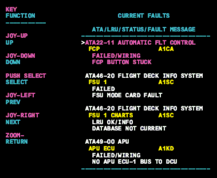
- On the cursor control panel, ensure the toggle switch is to the right and select Anti-Ice, ECS and Fuel buttons simultaneously. The MDC main menu should now be displayed on Display Unit #3.
- Using the joystick, select Current Faults (if the fault is active) or Aircraft History to research stored faults. From Aircraft History you can then select Fault Message History and locate the air condition fault logged.
- Select the MDC fault from the drop down below to provide additional information to assist in troubleshooting.
- When the IASC sees No Flow when it is demanded, it drives the FCV to the Full Open position. This can cause a PACK INLET OVERHEAT and R BLEED FAULT CAS messages with no MDC Fault Code.
- Run both engines at idle and monitor / record the bleed pressure parameters from the MDC.
- The Differential Pressure reading should be around 0.8 psid at idle and should react to engine thrust increase.
- If you notice that it is stuck at 0.0 psid and does not react to thrust increase, that Differential Pressure Sensor is to be suspected.
Left Engine (GOOD) Right Engine (BAD) Bleed Pressure: 49 psi 51 psi Differential Pressure: 0.8 psid 0.0 psid BAF: 9.5 lb/min 0.0 lb/min NOTE: If the Differential Pressure Sensor is stuck at 0 psid, it could cause the FCV to stay in the FULL OPEN position.
- If pressures and Differential are good, continue with next step.
- If you notice that it is stuck at 0.0 psid and does not react to thrust increase, that Differential Pressure Sensor is to be suspected.
- Perform a wiring check of the R BLEED (SDS14) PBA on the AIR CONDITIONING / BLEED CONTROL PANEL (PL17).
- If PBA is found defective, replace as required.
- If no defects are found, continue with next step.
- Perform a wiring check between the R BLEED (SDS14) PBA on the AIR CONDITIONING / BLEED CONTROL PANEL (PL17), IASC 2 (A56), the Data Concentrator Unit (DCU) (A14) and the R BLEED VALVE (V4).
- If wiring defects are found, repair defective wiring as required and do close out.
- If no defects are found, continue with next step.
- Swap IASC 2 with IASC 1. Is the fault still present?
- If YES, continue with next step.
- If NO, replace faulty IASC.
- Swap the right Bleed Valve with the left bleed valve to confirm faulty valve and replace if required.
- Do close out.