01/28/21
Message Overview:
| DDG Reference: | 36-20 |
| Pilot Action (QRH): | ICE 12-12 |
| System Description: | 30-12-00 |
| Schematic Diagram: | 30-12-00 L WING A/ICE LOOP SCHEMATIC R WING A/ICE LOOP SCHEMATIC |
| Wiring Diagram: | 30-12-05 |
Message Description:

Possible Causes:
- Both loops of the Wing Anti-Ice Ducting are detected failed
Troubleshooting Tips:
Advisory Wire/Service Bulletin:
- AW300-36-0310 - Bleed Loop Connector Cleaning Tool
- AW300-30-0354 - Potential Piccolo Tube Damage When Replacing a Bleed Loop Element
Forum Articles/Infoservice/Newsletter: None
- LH Wing/Fuse Bleed Loop Schematic and values
- RH Wing/Fuse Bleed Loop Schematic and values
- LH Pylon/Wing Bleed Loop Schematic and values
- RH Pylon/Wing Bleed Loop Schematic and values
Troubleshooting Guide for Bleed Loops
NOTE: If the bleed loop resistance value is within limits, try cleaning the bleed loop connections per AMM 51-25-00-110-801 and then reapply lubrication to the connections per AMM WM 20-20-00. Lubrication part number is called out in each bleed loop installation procedure. Run the aircraft after the cleaning and applying lubing procedure and see if the BLEED LOOP FAULT clears.
Quick Links:
| Component Location | AMM 36-21-00-992-801 |
| Operational Test of the Wing Anti-ice system | AMM 30-10-00-710-801 |
| Operational Test of the Bleed-Air Leak-Detection and Warning System | AMM 36-21-00-710-801 |
| Initiation Test of the Bleed-Air Leak-Detection Loops | AMM 36-21-00-740-801 |
| Resistance Check of the Bleed-Air Leak-Detection Loops | AMM 36-21-00-760-801 |
| Removal of the Wing−Root Leak−Detection Element | AMM 36-21-17-000-801 |
| Installation of the Wing−Root Leak−Detection Element | AMM 36-21-17-400-801 |
| Removal of the Wing−Middle Leak−Detection Element | AMM 36-21-17-000-802 |
| Installation of the Wing−Middle Leak−Detection Element | AMM 36-21-17-400-802 |
| Removal of the Wing−Outboard Leak−Detection Element | AMM 36-21-17-000-803 |
| Installation of the Wing−Outboard Leak−Detection Element | AMM 36-21-17-400-803 |
| Wiring - Maintenance Practices - ALL | SPM 20-12-00-02 |
| Wire Repair - Maintenance Practices - ALL | SPM 20-12-10-02 |
| Electrical Connectors - Maintenance Practice - ALL | SPM 20-20-00-02 |
Troubleshooting Recommendations:
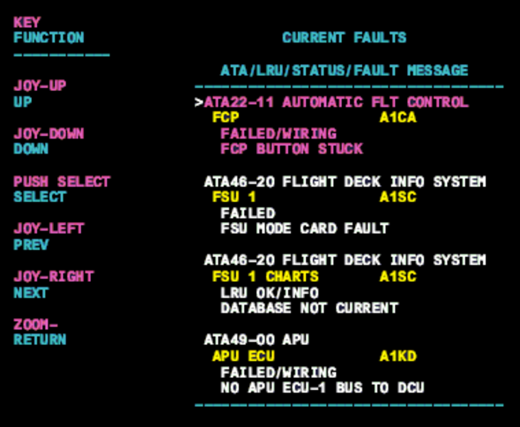
- Interrogate the MDC as follows:
- On the cursor control panel, ensure the toggle switch is to the right and select Anti-Ice, ECS and Fuel buttons simultaneously. The MDC main menu should now be displayed on Display Unit #3.
- Using the joystick, select Current Faults (if the fault is active) or Aircraft History to research stored faults. From Aircraft History you can then select Fault Message History and locate the fault. Going into advanced diagnostics will provide an equation id for the fault identified.
- Select the MDC fault or equation from the drop down below to provide additional information to assist in troubleshooting.