06/08/21
Message Overview:
Message Description:
The right FLOW CONTROL VALVE is detected failed in closed position or the right DPS has drifted.
NOTE: FCV switch disagree and DPS drift detection do not lead to Message.
Possible Causes:
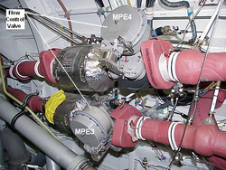
- Flow Control Valve (FCV) 2 (MPE4)
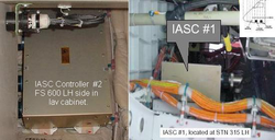
- Integrated Air System Controller (IASC) 2 (A56)
- Valve Switch
- Position Switch
- Associated Wiring
Troubleshooting Tips:
Advisory Wire/Service Bulletin: None
Forum Articles/Infoservice/Newsletter: None
Quick Links:
| Removal of the Integrated Air System (IAS) Controller | AMM 21-31-01-000-801 |
| Installation of the Integrated Air System (IAS) Controller | AMM 21-31-01-400-801 |
| Operational Test of the Integrated Air System (IAS) Controller | AMM 21-31-01-710-801 |
| Removal of the Flow Control Valve | AMM 21-51-09-000-801 |
| Deactivation of the Flow Control Valve | AMM 21-51-09-040-801 |
| Installation of the Flow Control Valve | AMM 21-51-09-400-801 |
| Activation of the Flow Control Valve | AMM 21-51-09-440-801 |
| Wiring - Maintenance Practices - ALL | SPM 20-12-00-02 |
| Wire Repair - Maintenance Practices - ALL | SPM 20-12-10-02 |
Troubleshooting Recommendations:
- Verify the closed commanded position when the flow control valve #2 MPE4 has failed.
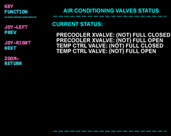
- Valve position can be viewed through the IASC LRU test pages. Interrogate the respective IASC to view valve position and bleed air pressure.
The indicated valve position can be verified against the Bleed Valve Status page by comparing the indication to the valves mechanical visual indicator. - Check the wiring between the #2 Integrated Air System Controller and the #2 flow control valve MPE4. If the switch is suspected, check the IASC #2 (A56) for proper switch indication of the effective flow control valve (FCV will provide a ground to the IASC for closed, and open circuit for the valve being open) IAW AWM 21-51-09.
- Swap or replace the suspected flow control valve or deactivate per the AMM. Reactivate per AMM.
- Suspect the #2 IAS controller, remove and replace per AMM.
- Operational test of the Integrated Air System (IAS) Controller.