11/05/25
Message Overview:
Message Name:
RESOLVER FAILED
Message Code:
B3-006405
Associated CAS:
| Reporting LRU: | COPILOT CW RES 3 |
| System Description: | 27-11-00 - Aileron Control System |
| Schematic Diagram: | 27-11-00-101 - Aileron/Trim Control System 20501 to 20936 27-11-00-102 - Aileron/Trim Control System 20937 and subs |
| Wiring Diagram: | 27-11-33 - Control-Wheel Position Sensor |
Message Description:
The Spoiler Electronic Control Unit 1 (SECU1) has detected a Co-pilot Control-Wheel Resolver 3 Fault.
Possible Causes:
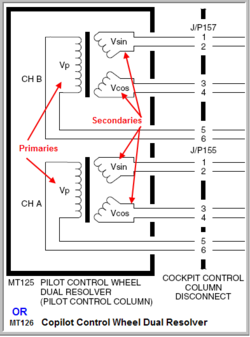
- Control-Wheel Position Sensor (RH) (MT126)
- Spoiler Electronic Control Unit 1 (SECU) (A118)
- Associated Wiring
Troubleshooting Tips:
Advisory Wire/Service Bulletin: None
Full Throttle Blog/Forum Articles/Infoservice/Newsletter: None
Flight Operation Notifications Manual (FONM): None
NOTES:
- Reset SECU1 circuit breaker "SPOILER CTRL 1" CBP1-B9 if any of the inboard MFS and GS #2, #4, #5 and #7 surface indication are amber or magenta.
- Reset SECU2 circuit breaker "SPOILER CTRL 2" CBP2-B9 if any of the inboard MFS and GS #1, #3, #6 and #8 surface indication are amber or magenta.
- It is not permissible to cycle the SECU 1 or 2 circuit breakers in the air.
Quick Links:
| Standard Aircraft Configuration for Maintenance | AMM 12-00-00-867-803 |
| Electrical/Electronic Safety Precautions | AMM 24-00-00-910-801 |
| Electrostatic-Discharge Safety Precautions | AMM 24-00-00-910-802 |
| Connect Electrical Power to the Aircraft | AMM 24-00-00-861-801 |
| Removal of the Control-Wheel Position Sensor | AMM 27-11-33-000-801 |
| Installation of the Control-Wheel Position Sensor | AMM 27-11-33-400-801 |
| Removal of the Spoiler Electronic-Control Unit (SECU) | AMM 27-61-05-000-801 |
| Installation of the Spoiler Electronic-Control Unit (SECU) | AMM 27-61-05-400-801 |
| Electronic Rigging of the Spoiler Electronic-Control Unit (SECU) | AMM 27-61-05-820-802 |
Troubleshooting Recommendations:
- Re-rig SECU1.
- If system checks are good, do close out.
- If fault remains, continue with next step.
- Interchange SECUs.
NOTE: Perform electronic rigging of both SECUs when either SECU is swapped or replaced. The intent is if a SECU that is being installed was previously rigged in a different location in the same aircraft or it is being installed in a different aircraft or the SECU is a spare part it requires electronic rigging per the instructions in AMM TASK 27-61-05-400-801 Installation of the Spoiler Electronic-Control Unit (SECU).
- If system checks are good, do close out.
- If fault remains, continue with next step.
- Check Resolver coil resistance. Primary coil approx. 242Ω, Secondary coil approx. 122Ω. Is resistance check as per tolerance?
From To Expected Result Result MT126 / J152 - 1 MT126 / J152 - 2 122Ω ± 5% MT126 / J152 - 3 MT126 / J152 - 4 122Ω ± 5% MT126 / J152 - 5 MT126 / J152 - 6 242Ω ± 5% - If YES, continue with next step.
- If NO, go to step 5.
- Do wiring check between Resolver 3 and SECU 1. Is wiring check as per expected result?
From To Expected Result Result MT126 / J152 - 1 A118AP1 - 1D Continuity MT126 / J152 - 2 A118AP1 - 1C Continuity MT126 / J152 - 3 A118AP1 - 1A Continuity MT126 / J152 - 4 A118AP1 - 1B Continuity MT126 / J152 - 5 A118AP1 - 6A Continuity MT126 / J152 - 6 A118AP1 - 6B Continuity - If YES, continue with next step.
- If NO, repair wiring and do close out.
- Replaced RVDT 3.
- Do close out.