01/22/25
Message Overview:
Message Name:
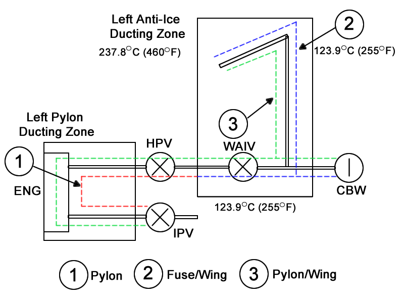
L PYL/FUS/WING DUCT LEAK
Message Code:
B3-007144
| Reporting LRU: | Dual Loop System |
| Associated CAS: | WING ANTI-ICE LEAK (Warning) |
| System Description: | 30-12-00 - Wing Anti-Ice System 36-20-00 - Indicating System |
| Schematic Diagram: | SSM 36-21-00-101 - Bleed-Air Leak-Detection System |
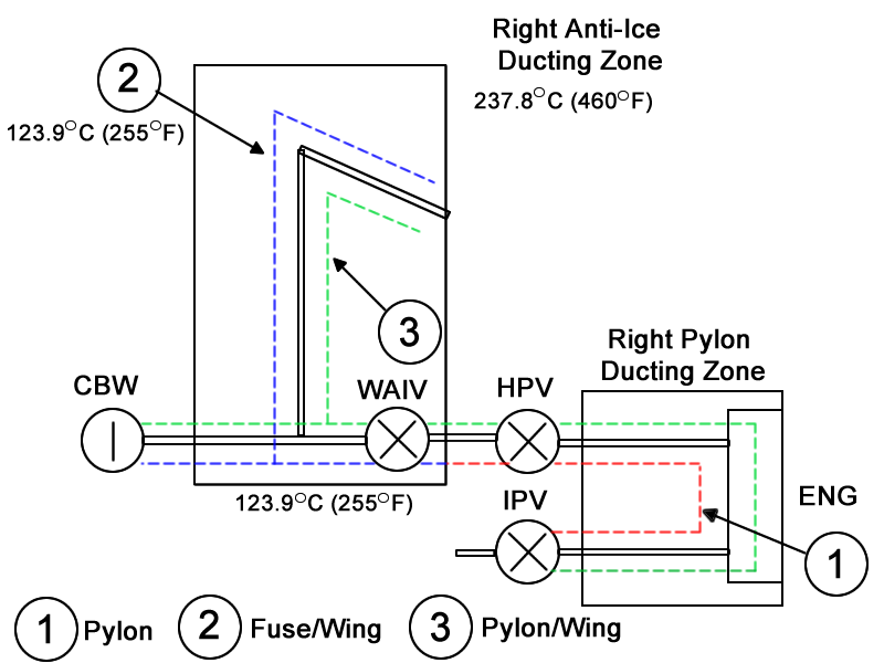
| Wiring Diagram: | WM 36-21-13-1_001 - Sheet 1 - Left Anti-Ice Fuselage Loop - ALL WM 36-21-15-1_001 - Sheet 1 - Right Anti-Ice Fuselage Loop - ALL |
Message Description:
This message will be displayed when one loop in a Dual Loop System detects an overheat for more than five minutes.
Possible Causes:
- Bleed Loop Routing
- Wing Leading Edge Temperature Sensor
- Dirty Wing Tip Connector
- Associated Wiring
Troubleshooting Tips:
Advisory Wire/Service Bulletin:
- AW300-36-0008 - "WING ANTI-ICE LEAK" EICAS Message During Climb
Full Throttle Blog/Forum Articles/Infoservice/Newsletter: None
Flight Operation Notifications Manual (FONM): None
NOTES:
Quick Links:
| Component Location | AMM 36-21-00-992-801 |
| Operational Test of the Bleed-Air Leak-Detection and Warning System | AMM 36-21-00-710-801 |
| Initiation Test of the Bleed-Air Leak-Detection Loops | AMM 36-21-00-740-801 |
| Resistance Check of the Bleed-Air Leak-Detection Loops | AMM 36-21-00-760-801 |
| Removal of the Left Bleed-Loop Element | AMM 36-21-01-000-801 |
| Installation of the Left Bleed-Loop Element | AMM 36-21-01-400-801 |
| Fenwal Safety Systems | CMM 26-14-47 |
| Safety Precautions - Maintenance Practices - ALL | SPM 20-00-01-02 |
| Wiring - Maintenance Practices - ALL | SPM 20-12-00-02 |
| Wire Repair - Maintenance Practices - ALL | SPM 20-12-10-02 |
| Electrical Connectors - Maintenance Practice - ALL | SPM 20-20-00-02 |
Troubleshooting Recommendations:
- Interrogate the Leak Event Location on both IASC 1 and IASC 2 channel B with the Maintenance Diagnostic Computer to determine the exact location of the leak.
- Once the percentage value is obtained from the MDC, refer to mapping tool representing all potential bleed leak locations in term of percentage, for each metered bleed air hole and LRU connections point. This will help to quickly troubleshoot source of the leak.
WING ANTI-ICE LEAK B3-007144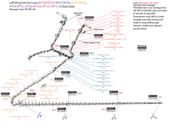
NOTE: Before replacing a loop always look at the loop for routing, ensure loop is not too close to the plumbing or the bleed hole on a valve. - Inspect for foil backing on the insulation in the leading edge. Ensure the Foil is not pealing and wrapping itself around an element.
- A short and a leak can be coming from the same location. This scenario can create confusion as the IASC may misinterpret the resistance value of the short.
- If no leaks are found then use a Tegam meter to check capacitance and inductance between the inner and outer conductor of the corresponding loop. Perform the impedance check per the Leak Detection How To.
- Replace affected loop as required.
- Do close out.