03/26/25
Message Overview:
Message Name:
REFUEL DEFUEL SOV WILL NOT OPEN IN MANUAL MODE
| Message Code: | 282OBS005 |
| Effectivity: | AIRCRAFT 20501 - 20999 |
| System: | Pressure Refuel/Defuel |
| Associated CAS: | None |
| System Description: | 28-23-00 - Refuel/Defuel System |
| Schematic Diagram: | SSM 28-41-00-101 - Fuel Management and Quantity Gauging System (FMQGS) |
| Wiring Diagram: | WM 31-45-07-1_001 - Sheet 1 - Integrated Avionics Processor System (R-GP-5) - [20501 TO 20886, 20888 TO 20890, 20896 TO 20898] |
Message Description:
One or both refueling Shutoff Valve (SOV) will not open in manual mode.
Possible Causes:
- Refuel/Defuel Manifold (A59)/Left Refuel/Defuel Shutoff Valve
- Refuel/Defuel Manifold (A59)/Right Refuel/Defuel Shutoff Valve
- Left Fuel Tank High Level Sensor (MT15)
- Right Fuel Tank High Level Sensor (MT16)
- Refuel/Defuel Panel (PL41)
- Fuel System Computer Unit (A57)
- Associated Wiring
Troubleshooting Tips:
Advisory Wire/Service Bulletin: None
Full Throttle Blog/Forum Articles/Infoservice/Newsletter: None
Flight Operation Notifications Manual (FONM): None
NOTES:
- Fill the Detailed FQGC Troubleshooting Report if Fuel Quantity Gauging Computer (FQGC) pn 738360-1-2 is replaced
Quick Links:
| Pressure Refueling | AMM 12-11-01-650-801 |
| Suction Defueling | AMM 12-11-09-650-801 |
| Removal of the Refuel/Defuel Control Panel | AMM 28-23-01-000-801 |
| Installation of the Refuel/Defuel Control Panel | AMM 28-23-01-400-801 |
| Operational test of the Refuel/Defuel Control Panel | AMM 28-23-01-710-801 |
| Removal of the Refuel/Defuel Manifold | AMM 28-23-09-000-801 |
| Installation of the Refuel/Defuel Manifold | AMM 28-23-09-400-801 |
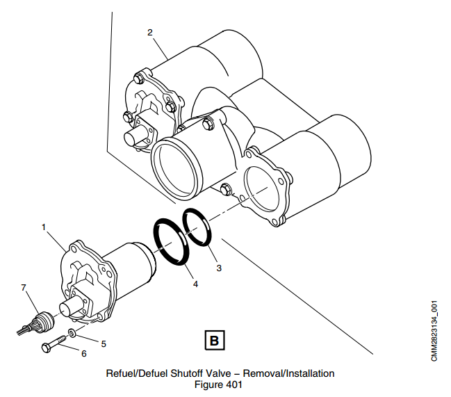
| Removal of the Refuel/Defuel Shutoff Valve | AMM 28-23-13-000-801 |
| Installation of the Refuel/Defuel Shutoff Valve | AMM 28-23-13-400-801 |
| Removal of the Fuel Quantity Computer | AMM 28-41-01-000-801 |
| Installation of the Fuel Quantity Computer | AMM 28-41-01-400-801 |
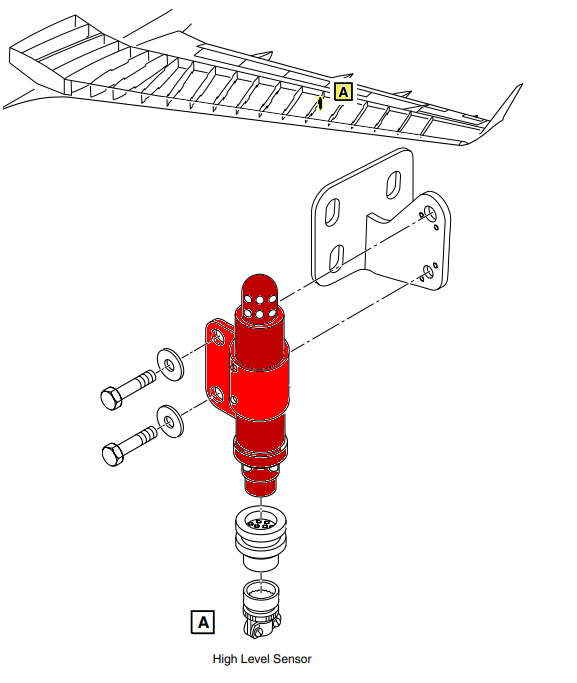
| Removal of the High Level Sensor | AMM 28-41-17-000-801 |
| Installation of the High Level Sensor | AMM 28-41-17-400-801 |
| Safety Precautions - Maintenance Practices - ALL | SPM 20-00-01-02 |
| Wiring - Maintenance Practices - ALL | SPM 20-12-00-02 |
| Wire Repair - Maintenance Practices - ALL | SPM 20-12-10-02 |
| Electrical Connectors - Description and Operation - ALL | SPM 20-20-00-00 |
Troubleshooting Recommendations:
- Make sure that RDCPC CB6-C5 (REFUEL DEFUEL VALVES) and CB6-C4 (REFUEL DEFUEL CTL) circuit breakers are pushed in.
- Make sure there are no FUEL QTY FAULT/FAIL EICAS messages or any MAGENTA indications are present on the fuel synoptic page.
- If a fault is found, carry out appropriate troubleshooting.
- Verify MDC CURRENT FAULTS for 'L(R) TNK HI LVL' fault (B3-007142/B3-007864).
- If fault code is present, carry out B3-007142/B3-007864 troubleshooting.
- If fault code is not present, continue with next step.
- Select the active MDC fault or equation from the drop down below prior to following the troubleshooting below.
- If any of the fault codes, listed on that page are present on the aircraft, troubleshoot these fault codes first.
- If none of the fault codes are present, continue with next step.
- On Refuel/Defuel Panel, verify that both H. LEVEL DETECTOR lights are OFF before initiating the High Level Test.
NOTE: Extremely low ambient temperature (below -40°C (-40°F)) can create a false high level indication and prevent refueling.- If one H. LEVEL DETECTOR light is ON and its tank is not full, interchange high level Sensors.
- If problem follows, replace faulty high level sensor.
- If problem does not follow, verify wiring between high level sensor and FQGC.
- If wiring is found serviceable, go to next step.
- If both H. LEVEL DETECTOR lights are ON and their respective tanks are not full, go to next step.
NOTE: A failure of a SOV to OPEN shall not be considered faulty if the corresponding tank was already filled up to the High Level Sensor at initiation of the test.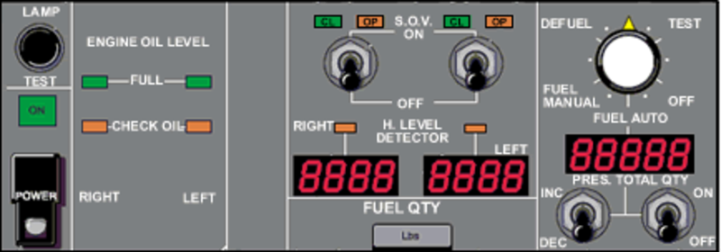
- If one H. LEVEL DETECTOR light is ON and its tank is not full, interchange high level Sensors.
- Re-rack the Fuel Quantity Gauging Computer (FQGC). Is the fault message still present?
- If YES, go to next step.
- If NO, do close out.
- Replace the Fuel Quantity Gauging Computer (FQGC).
- Try refueling in manual mode and observe the SOV indication lights on the R/D Panel.
- During the test, if one SOV does not open, do the following:
- Verify that the fueling hose was pressurized to 50 psi. If not, pressurize the fueling hose to 50 psi and carry out step 5 again.
- If raising the pressure to 50 psi opens the faulty valve, consider replacing the valve.
- Access Refuel/Defuel SOV through access panel 181BL.
- Have a person close to the SOV that will listen for a solenoid clicking.
- Set the Refuel/Defuel control panel power switch to ON.
- Set the fuel selector knob to FUEL MAN.
- Set the SOV toggle switch of the SOV that did not open to ON.
- If the SOV solenoid was heard clicking and fuel quantity did not rise, replace SOV.
- If the SOV solenoid did not click, go to next step.
- Disconnect the fueling hose from the aircraft.
- Set the Refuel/Defuel control panel power switch to ON.
- Set the fuel selector knob to DEFUEL.
- Set the SOV toggle switch of the SOV that did not open to ON.
- If the SOV solenoid did not click, replace SOV.
- If the SOV solenoid was heard clicking, verify wiring as per the following table:
From To Result A57BP1-20 A59P2-3 A57BP1-18 A59P1-3 - If wiring is found serviceable, replace FQGC.
- Verify that the fueling hose was pressurized to 50 psi. If not, pressurize the fueling hose to 50 psi and carry out step 5 again.
- During the test, if neither valves opened, do the following:
- Remove R/D Panel from the aircraft.
- Set the R/D Panel to the following configuration:
POWER SWITCH ON ROTARY SELECTOR FUEL MAN - On the R/D Panel back connector, check for continuity while tapping on the rotary selector as follows:
From To Result Result PL41J1-13 PL41J1-3 PL41J1-8 PL41J1-3 - If there is no continuity, replace R/D Panel.
- If there is continuity, replace FQGC.
- Do close out.