12/01/23
Message Overview:
| DDG Reference: | None |
| Pilot Action (QRH): | GEAR 10-8 |
| System Description: | 32-43-00 - Brake Control System |
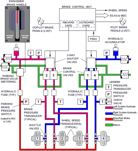
| Schematic Diagram: | SSM 32-43-00-101 - Brake Control System |
| Wiring Diagram: | WM 32-43-17-1_001 - Sheet 1 - Brake Pressure Transducers - ALL |
Message Description:
The Outboard Brake Hydraulic System/Accumulator pressure is detected below 1, 400 psi.
Possible Causes:
- Right Hydraulic System 2 Pressure Switch (S98)
- Outboard Brake Accumulator
- Nitrogen Leakage(s)
- Outboard Brake Shut-off Valve (MPE28)
- Outboard Brake Check Valve
- Outboard Brake Hydraulic System Component(s) Leakage(s)
- Associated Wiring
Troubleshooting Tips:
Advisory Wire/Service Bulletin:
- AW300-32-0136 - Parking Brake Pressure Depletion
- AW300-32-0305 - Brake Accumulator Low Pressure CAS Message
Forum Articles/Infoservice/Newsletter: None
NOTE:
- In order to consider the Outboard Brake system faulty when to the OUTBD BRAKES PRESS LO is posted on the EICAS, the system must be tested with the Outboard Brake SOV in the closed position (OUTBD BRAKES CB pulled or Outboard SOV connector disconnected). Otherwise, DO NOT suspect defective(s) component(s) in that system.
Fault Confirmation Procedure (OUTBD BRAKE PRESS LO)
- Disconnect the Outboard BSOV electrical connector MPE28P1.
- Pressurize right hydraulic system.
- Wait 5 minutes for the accumulator pressure to stabilize.
- Confirm the accumulator pressure on HYD page is showing a green "PRESS NORM".
- Depressurize right hydraulic system.
- Wait 1 hour and re-verify status of OUTBD BRAKES on HYD page.
- If the pressure is showing in amber "PRESS LO" = The test confirms a failure with the Outboard Brake System.
- If pressure remains green "PRESS NORM" = No maintenance action is required.
Quick Links:
| Quantity check of the Brake, Downlock Assist and Auxiliary hydraulic System Accumulators | AMM 12-12-00-610-803 |
| Servicing of the Brake, Downlock Assist and Auxiliary Hydraulic System Accumulators | AMM 12-12-00-614-801 |
| Removal of the Brake Shutoff Valve | AMM 32-43-25-000-801 |
| Installation of the Brake Shutoff Valve | AMM 32-43-25-400-801 |
| Removal of the Brake Check Valve | AMM 32-43-29-000-801 |
| Installation of the Brake Check Valve | AMM 32-43-29-400-801 |
| Removal of the Brake Accumulator | AMM 32-43-37-000-801 |
| Installation of the Brake Accumulator | AMM 32-43-37-400-801 |
| Removal of the Brake Pressure Switch | AMM 32-43-45-000-801 |
| Installation of the Brake Pressure Switch | AMM 32-43-45-400-801 |
| Functional Test of the Emergency/Parking Brake for Pressure Retention | AMM 32-44-00-720-801 |
| Wiring - Maintenance Practices - ALL | SPM 20-12-00-02 |
| Wire Repair - Maintenance Practices - ALL | SPM 20-12-10-02 |
Troubleshooting Recommendations:
- Perform the fault confirmation procedure above.
- If the test passes, do close out.
- If the test fails, continue with next step.
- Perform a visual inspection of the Outboard Brakes hydraulic system components for leak(s). Repair or replace as required and perform the fault confirmation test again.
- If the fault confirmation test passes, do close out.
- If the fault confirmation test fails, continue with next step.
- Perform the quantity check of the Brake, Downlock Assist and Auxiliary hydraulic System Accumulators for the Outboard Brake Accumulator.
- If quantity check passes, go to step 8.
- If quantity check fails, continue with next step.
- Perform the "Quantity check of the Brake, Downlock Assist and Auxiliary hydraulic System Accumulators" (AMM 12-12-00-610-803) for the Outboard Brake Accumulator.
- Wait 1 hour after the servicing and do another quantity check of the Brake, Downlock Assist and Auxiliary Hydraulic System Accumulators for the Outboard Brake Accumulator.
- If quantity check passes, go to step 8.
- If quantity check fails, continue with next step.
- Inspect the Outboard Brake Accumulator charging valve, pressure gauge and the nitrogen lines that connect with the Outboard Brake Accumulator end fitting for leakage.
- If no leakage is found, go to step 8.
- If leakage is found, continue with next step.
- Replace the leaking component(s) and perform the fault confirmation procedure.
- If the test passes, do close out.
- If the test fails, continue with next step.
- Access and disconnect the right hydraulic system 2 pressure switch (right landing gear bay) connector S98P1. Pressurize the right hydraulic system and perform a continuity check of the switch as follows:
From To Result S98J1-2 S98J1-3 - If there is continuity, depressurize the hydraulic system and continue with next step.
- If there is no continuity, replace the pressure switch.
NOTE: You may interchange the right hydraulic system pressure switch with the left hydraulic pressure switch to confirm faulty component.
- Perform a continuity check between the pressure switch and the BCU as follows:
From To Result S98J1-2 A67P1-40 S98J1-3 A67P1-43 NOTE: Make sure the wires are not short circuited to ground also.
- If there is continuity, continue with next step.
- If there is no continuity, repair defective wiring as required and do close out.
- Replace the Outboard Brake Accumulator and perform the fault confirmation procedure.
- If the test passes, do close out.
- If the test fails, continue with next step.
- Replace the Outboard Brake Shutoff Valve and perform the fault confirmation procedure.
- If the test passes, do close out.
- If the test fails, continue with next step.
NOTE: The Shut-off Valve could have an internal leak. It could be confirmed by swapping the Shut-off Valves or by opening the hydraulic lines connected downstream of the suspected component (a good understanding of the Brake System Schematic is required for this option).
- Replace the Outboard Brake Check Valve.
- Do close out.