03/26/25
Message Overview:
Message Name:
REFUELING NOT AVAILABLE IN AUTOMATIC MODE
| Message Code: | 282OBS006 |
| Effectivity: | AIRCRAFT 20501 - 20999 |
| System: | Fuel |
| Associated CAS: | None |
| System Description: | 28-23-00 - Refuel/Defuel System |
| Schematic Diagram: | SSM 28-23-00-101 - Refuel/Defuel System |
| Wiring Diagram: | WM 28-23-13-1_001 - Sheet 1 - Refuel/Defuel Shutoff Valve - ALL |
Message Description:
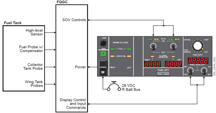
Arming of the Refuel System is controlled by the guarded POWER switch pushed up. The power ON indicator lamp (green) illuminates, Refueling is preceded by the test sequence. When Rotary Switch is set to TEST, the Fuel Quantity Gauging Computer (FQGC) initiates a predefined Fuel Quantity and Gauging Computer (FQGC) controlled sequence for detecting malfunction of refueling equipment (Refuel/Defuel Shutoff Valves (SOVs), High Level Sensors (HLSs), ) If no failure is reported through the HLS or SOV Lamps, the Rotary Switch is set to FUEL AUTO. Then, the required total aircraft fuel quantity is selected with the INC./DEC. Toggle Switch on the five-digit display by operating the INC/DEC Switches, The refueling operation is initiated by setting the refueling start Toggle Switch to ON, The refueling is controlled by the FQGC commanding the Refuel/Defuel SOVs shut when the selected contents are reached. In case of automatic refueling failure.
- Pressure refueling is accomplished
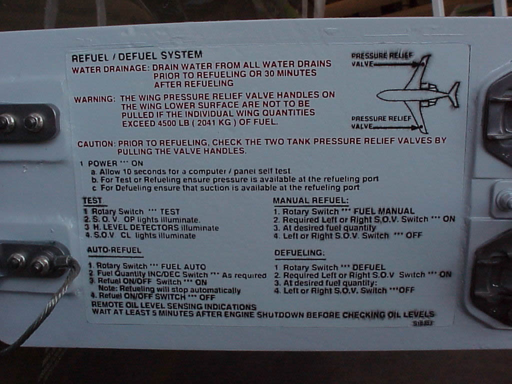
- Refuel Procedures Quick Reference Chart
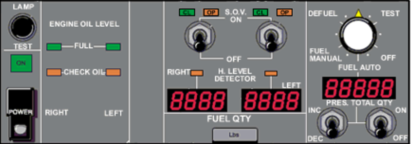
- Refuel Placard
- System Block
Possible Causes:
- Fuel Truck Supply pressure
- Refuel/Defuel Manifold (A59)
- Refuel/Defuel Manifold (A59)/Left Refuel/Defuel Shutoff Valve
- Refuel/Defuel Manifold (A59)/Right Refuel/Defuel Shutoff Valve
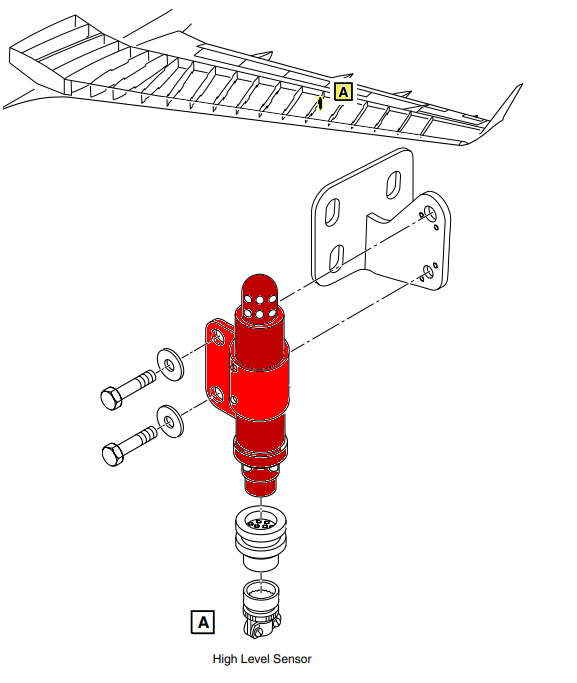
- Left Fuel Tank High Level Sensor (MT15)
- Right Fuel Tank High Level Sensor (MT16)
- Fuel System Computer Unit (A57)
- Refuel/Defuel Panel (PL41)
- Associated Wiring
Troubleshooting Tips:
Advisory Wire/Service Bulletin:
- AW300-28-0398 - SmartFix Plus Fuel System Troubleshooting Updates
- AW300-28-0138 - Fuel Tank Sumping
Full Throttle Blog/Forum Articles/Infoservice/Newsletter: None
Flight Operation Notifications Manual (FONM): None
NOTES:
- Fill the Detailed FQGC Troubleshooting Report if Fuel Quantity Gauging Computer (FQGC) pn 738360-1-2 is replaced
Quick Links:
| Pressure Refueling | AMM 12-11-01-650-801 |
| Suction Defueling | AMM 12-11-09-650-801 |
| Removal of the Refuel/Defuel Control Panel | AMM 28-23-01-000-801 |
| Installation of the Refuel/Defuel Control Panel | AMM 28-23-01-400-801 |
| Operational test of the Refuel/Defuel Control Panel | AMM 28-23-01-710-801 |
| Removal of the Refuel/Defuel Manifold | AMM 28-23-09-000-801 |
| Installation of the Refuel/Defuel Manifold | AMM 28-23-09-400-801 |
| Removal of the Refuel/Defuel Shutoff Valve | AMM 28-23-13-000-801 |
| Installation of the Refuel/Defuel Shutoff Valve | AMM 28-23-13-400-801 |
| Removal of the Fuel Quantity Computer | AMM 28-41-01-000-801 |
| Installation of the Fuel Quantity Computer | AMM 28-41-01-400-801 |
| Removal of the High Level Sensor | AMM 28-41-17-000-801 |
| Installation of the High Level Sensor | AMM 28-41-17-400-801 |
| Safety Precautions - Maintenance Practices - ALL | SPM 20-00-01-02 |
| Wiring - Maintenance Practices - ALL | SPM 20-12-00-02 |
| Wire Repair - Maintenance Practices - ALL | SPM 20-12-10-02 |
| Electrical Connectors - Description and Operation - ALL | SPM 20-20-00-00 |
Troubleshooting Recommendations:
- On the Right DC Power Center (RDCPC), make sure Circuit Breaker (CB) CB6-C4 REFUEL/DEFUEL CONTROL and CB6-C5 REFUEL/DEFUEL VALVES are set to IN.
- If the FUEL QUANTITY FAULT (Advisory) or FUEL QUANTITY FAIL (Caution) CAS messages are displayed, troubleshoot these messages first.
- Select the active MDC fault or equation from the drop down below prior to following the troubleshooting below.
- If any of the fault codes, listed on that page are present on the aircraft, troubleshoot these fault codes first.
- If none of the fault codes are present, continue with next step.
- Disconnect and clean connector PL41P1 on the Refuel/Defuel Control Panel (RDCP) with contact cleaner and allow to dry. Is the fault still present?
- If YES, continue with next step.
- If NO, do close out.
- Allow enough time (approx. 10 sec) for the RDCP self-test to complete.
- On Refuel/Defuel Panel, verify that both H. LEVEL DETECTOR lights are OFF before initiating the High Level Test.
NOTE: Extremely low ambient temperature (below -40°C (-40°F)) can create a false high level indication and prevent refueling.- If one H. LEVEL DETECTOR light is ON and its tank is not full, interchange high level Sensors.
- If problem follows, replace faulty high level sensor.
- If problem does not follow, verify wiring between high level sensor and FQGC.
- If wiring is found serviceable, go to next step.
- If both H. LEVEL DETECTOR lights are ON and their respective tanks are not full, go to next step.
NOTE: A failure of a SOV to OPEN shall not be considered faulty if the corresponding tank was already filled up to the High Level Sensor at initiation of the test.
- If one H. LEVEL DETECTOR light is ON and its tank is not full, interchange high level Sensors.
- Re-rack the Fuel Quantity Gauging Computer (FQGC). Is the fault message still present?
- If YES, go to next step.
- If NO, do close out.
- Replace the Fuel Quantity Gauging Computer (FQGC).
- Perform refueling in manual mode (AMM 12-11-01-650-801) and observe the SOV indication lights on the R/D Panel.
- During the SOV test, if one of the SOVs does not open, continue with next step.
- If none of the SOVs open, go to step 19
- Verify that the refueling source was pressurized to the higher end of the pressure range indicated in the AMM pressure refueling task. If not, pressurize the refueling source to 50 psi and redo the previous step.
- If raising the pressure opens the faulty valve, consider replacing the valve.
- If there is no change, continue with next step.
- Access Refuel/Defuel SOV through access panel 181BL.
- Have a second person standing close to the SOV and listen for a solenoid clicking sound.
- Set the Refuel/Defuel control panel power switch to ON.
- Pressurize the refueling source o the higher range of the AMM allowed pressure.
- On the RDCP set the fuel selector knob to FUEL MAN.
- Set the SOV toggle switch of the affected SOV to ON.
- If the SOV solenoid was heard clicking and fuel quantity did not rise, replace the SOV.
- If the SOV solenoid did not click, continue with next step.
- Perform a wiring check between the affected SOV and the FQGC as follows:
From To Result A57BP1-20 A59P2-3 A57BP1-18 A59P1-3 - If wiring defects are found, repair defective wiring as required and do close out.
- If no defects are found, continue with next step.
- Replace the affected SOV. Is the fault still present?
- If YES, replace the FQGC.
- If NO, do close out.
- Remove the RDCP.
- Set the RDCP to the following configuration:
POWER SWITCH ON ROTARY SELECTOR FUEL AUTO REFUEL ON/OFF SWITCH ON - On the R/D Panel back connector, check for continuity while tapping on the rotary selector as follows:
From To Expected Result Result PL41J1-35 PL41J1-3 Continuity - If there is no or intermittent continuity, replace R/D Panel.
- If there is continuity, continue with next step.
- Verify wiring between FQGC connector and RDCP connector as follows:
From To Result A57BP1-4 PL41P1-35 - If wiring defects are found, repair defective wiring as required and do close out.
- If no defects are found, replace the FQGC and do close out.
- Do close out.