

10/04/21
Message Overview:
Message Description:
The channel A of the COMPRESSOR DISCHARGE TEMPERATURE SENSOR is detected failed.
Possible Causes:
- Compressor Discharge Temperature (CDT) Sensor (MT29)
- Integrated Air System Controller 1 (IASC1) (A55)
- Associated Wiring
Troubleshooting Tips:
Advisory Wire/Service Bulletin: None
Forum Articles/Infoservice/Newsletter: None
Fault Confirmation Procedure:
- Message# = 2
- Fault Logged = AIR,TAXI
- Status = FAILED/WIRING
- Timer = 7
- Logic = IAS1A-52
- {Term Definitions}
- IAS1A-52 XX 353 00 EXCT XXXX-XXXX XXXX-XXXT XXXX-XXXX 353A:17; COMP DISCHRG TEMP SNSR
Quick Links:
| Removal of the Integrated Air System (IAS) Controller | AMM 21-31-01-000-801 |
| Installation of the Integrated Air System (IAS) Controller | AMM 21-31-01-400-801 |
| Removal of the Compressor Discharge Temperature Sensor | AMM 21-52-17-000-801 |
| Installation of the Compressor Discharge Temperature Sensor | AMM 21-52-17-400-801 |
| Wiring - Maintenance Practices - ALL | SPM 20-12-00-02 |
| Wire Repair - Maintenance Practices - ALL | SPM 20-12-10-02 |
| Electrical Connectors - Maintenance Practice - ALL | SPM 20-20-00-02 |
Troubleshooting Recommendations:
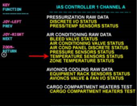
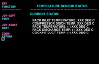
- Use the MDC LRU TEST to view the Integrated Air System Controller (IASC) 1 and IASC 2 TEMPERATURE SENSORS STATUS pages. Compare and record the COMPRESSOR DISCH TEMP value for both IASC.
- Access the Compressor Discharge Temperature Sensor (CDTS) connector (MT29P1). Inspect the connector for proper installation, damage or contaminants.
- If defects are found, rectify as required and do close out.
- If no defects are apparent, continue with next step.
- Perform a wiring check between the CDTS (MT29) and IASC 1 (A55) as follows:
From To Result MT29P1-1 A55P1-26 MT29P1-3 A55P1-49 NOTE: Make sure to check for short circuit to ground also.
- If wiring defects are found, repair defective wiring as required and do close out.
- If no defects are found, continue with next step.
- Replace the CDTS (MT29). Is the fault still present?
- If YES, continue with next step.
- If NO, do close out.
- Interchange IASC 1 with IASC 2 to confirm faulty unit and replace if required.
- Do close out.

