01/13/25
Message Overview:
Message Name:
LEFT WINDSHIELD FAILED
Message Code:
B3-007146
Associated CAS:
| Reporting LRU: | LEFT WINDSHIELD |
| System Description: | 30-41-00 - Windshield And Side Window Anti-ice |
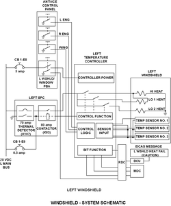
| Schematic Diagram: | 30-41-00 - Windshield And Side Window Anti-ice |
| Wiring Diagram: | 30-41-01 - Windshield Temperature Controllers 30-41-13 - Windshield Heater DCU Interface |
Message Description:
The Left Windshield Temperature Controller (LWTC) has detected a failed heater element, temperature sensor or faulty wiring.
Possible Causes:
- Left Windshield (MPE57)
- Left Windshield Temperature Controller (A157)
- Remote Data Concentrator (RDC) (A13)
- Associated Wiring
Troubleshooting Tips:
Advisory Wire/Service Bulletin:
- AW300-30-0328 - Windshield Heat Fail CAS Messages
- AW300-30-0418 - Windshield and Side Window Temperature Sensor Drift
Full Throttle Blog/Forum Articles/Infoservice/Newsletter:
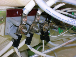
- A100-30-03 - SPECIAL CHECK - WINDSHIELD AND SIDE WINDOW ANTI-ICE - TORQUING OF ELECTRICAL CONNECTIONS AT TERMINAL BLOCKS TB3 AND TB4; GROUND STUDS GS2269, GS2270, GS2273 AND GS2274; WINDSHIELD TERMINALS G, H, L1 AND L2; AND SIDE WINDOW TERMINALS P AND G
Flight Operation Notifications Manual (FONM): None
NOTES:
- The Windshield Temperature Controllers and Side Window Temperature Controllers are different part numbers.
- The L and R Window Temperature Control circuits and parts (including relays) can be used for troubleshooting if needed (interchange).
- The resistance of windshield sensor check (Rmin < normal resistance < Rmax) Maximum expected sensor resistance using the following formula: Rmax = 0.6*x + 275 Ω, where x is the ambient temp of the windshield in °F. Minimum expected sensor resistance using the following formula: Rmin = 0.8*x + 248 Ω, where x is the ambient temp of the windshield in °F, where °F= (°C * 1.8) + 32.
- In case of transparency removal, fill the Transparency return form, send a copy to the CRC and attach a copy to the returned unit.
Quick Links:
| Standard Aircraft Configuration for Maintenance | AMM 12-00-00-867-803 |
| Electrical/Electronic Safety Precautions | AMM 24-00-00-910-801 |
| Electrostatic-Discharge Safety Precautions | AMM 24-00-00-910-802 |
| Connect Electrical Power to the Aircraft | AMM 24-00-00-861-801 |
| Remove the Electrical Power from the Aircraft | AMM 24-00-00-861-802 |
| Removal of the Windshield Temperature Controller | AMM 30-41-01-000-801 |
| Installation of the Windshield Temperature Controller | AMM 30-41-01-400-801 |
| Removal of the Remote Data Concentrator (RDC) | AMM 31-41-05-000-802 |
| Installation of the Remote Data Concentrator (RDC) | AMM 31-41-05-400-802 |
| Removal of the Windshield | AMM 56-11-01-000-801 |
| Installation of the Windshield | AMM 56-11-01-400-801 |
Troubleshooting Recommendations:
- Confirm status of circuit breaker. If the circuit breaker is open, find out the reason before resetting. If there is other Secondary Power Center related faults in the MDC, look for commonalities with the associated power bus (L MAIN BUS).
- Locate and inspect ground studs GS2269. Make sure that the electrical connections at ground studs GS2269 are tightened.
- Locate and inspect Terminal block TB3, make sure that the electrical connections at Windshield TB3 is tightened.
- Perform a visual inspection of all Terminal lugs on the windshield and the WTC for improper installation or damage. Repair if required.
- Perform the resistance test of L Windshield Sensors as follows:
NOTE: To perform this test correctly, you must disconnect the wires from the windshield terminals or from Terminal Block 3 (TB3) if you are measuring from that point.
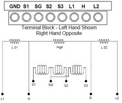
Condition S1 - SG (Resistance) S2 - SG (Resistance) S3 - SG (Resistance) at 65°F 307 ±5 Ω (nominal) 307 ±5 Ω (nominal) 307 ±5 Ω (nominal) at 80°F 318 ±5 Ω 318 ±5 Ω 318 ±5 Ω OPEN Circuit > 500 Ω > 500 Ω > 500 Ω SHORT Circuit < 225 Ω < 225 Ω < 225 Ω - If a sensor reads outside the nominal values without being OPEN/SHORT, if a variation of resistance is noticed for the same temperature refer to IS Modsum IS100-30-0002/02/03/05 and AW300-30-0418. An OPEN/SHORT sensor will be rejected by the controller and the system will continue to be serviceable.
- If resistance is within tolerance, continue with next step.
- Perform a wiring check between the left Temperature Controller and the left Windshield Sensors as follows:
From To Result A157-C MPE57-S1 (TB3 pin 4) A157-P MPE57-SG (TB3 pin 7) A157-N MPE57-S2 (TB3 pin 5) A157-L MPE57-SG (TB3 pin 7) A157-D MPE57-S3 (TB3 pin 6) A157-R MPE57-SG (TB3 pin 7) - If wiring defects are found, repair defective wiring as required.
- If no defects are found, continue with next step.
- Perform the resistance test of L Windshield Heater Elements as follows:
NOTE: To perform this test correctly, you must disconnect the wires from the windshield terminals or from Terminal Block 3 (TB3) if you are measuring from that point.NOTE: While we highly recommend to use a mili-ohmmeter/bonding tester. An ohmmeter at lowest range can be use if resistance are added (e.g. resistance from L1 to GND ) As resistance H to L1 may be too low for some ohmmeters.
Zone From To Open Circuit Short Circuit Result Zone A MPE57-H (TB3 pin 2) Ground > 0.454 Ω < 0.410 Ω Zone B MPE57-H (TB3 pin 2) L1 > 0.113 Ω < 0.093 Ω Zone C MPE57-L2 (TB3 pin 3) Ground > 2.207 Ω < 1.805 Ω - If resistance is within tolerance, continue with next step.If resistance is out of tolerance, replace left windshield.
- Perform a wiring check between the Left WTC and the left windshield Heater elements as follows:
From To Result A157-LO1 MPE57-L1 (TB3 pin 1) A157-HI MPE57-H (TB3 pin 2) A157-LO2 MPE57-L2 (TB3 pin 3) - If wiring defects are found, repair defective wiring as required.
- If no defects are found, continue with next step.
- Interchange the left WTC with the right WTC. Is the fault still present?
- If YES, continue with next step.
- If NO, replace defective WTC.
- Perform a wiring check between the L WTC and Remote Data Concentrator.
- If wiring defects are found, repair defective wiring as required.
- If no defects are found, continue with next step.
- Replace the Remote Data Concentrator (RDC).
- Do close out.