


08/16/16
Overview
The cabin-pressure control system keeps the pressure necessary, in the pressurized compartments of the aircraft, for the safety of the passengers. It also keeps the difference between the inside and outside pressure at the correct value to protect the aircraft structure.
The air conditioning system supplies the cabin-pressure control system with conditioned air to pressurize the aircraft. Two outflow valves open and close to control the pressure .
The PRESSURIZATION control panel and the cabin pressure controllers control the outflow valves automatically (AUTO) or manually (MAN). The cabin-pressure control system keeps the differential pressure and the maximum altitude pressure in the passenger compartment, lavatory, galley, flight compartment and baggage compartment in limits. The cabin-pressure control system uses two automatic modes (AUTO 1 and AUTO 2) and one manual mode (MAN). Each AUTO system includes one cabin pressure controller which controls the outflow valves. In the MAN mode, the crew controls both outflow valves directly through the PRESSURIZATION control panel. When the system becomes unserviceable, the safety system overrides the AUTO and MAN modes and controls the pressure through the outflow valves and the safety valves.
Only one automatic mode is in operation while the other automatic mode is in standby. If a malfunction occurs in the active system, a smooth transfer from one automatic mode to the other will automatically occur. The cabin pressure controller drives the two electrical outflow valves through the automatic drive mechanism of the outflow valve actuator.
In the manual mode, cabin pressure is manually controlled with the MAN ALT switch on the pressurization control panel. The switch directly controls the two outflow valves. The manual drive mechanism of the outflow valve actuator controls each outflow valve. When the two automatic modes are defective, the AUTO/MAN switch/light on the pressurization control panel must be set to MAN. The MAN ALT switch then controls the pressure.
In both AUTO modes and in Manual mode, the cabin pressure control system provides indications of the cabin pressure parameters which are displayed on EICAS Status page.


Cabin Pressurization Panel
The pressurization control panel is installed on the overhead panel in the flight compartment. It contains the Push Button Annunciators (PBAs) and switches necessary to control the cabin pressure control system in both AUTO modes and in MANUAL mode. Four relays, two relays for emergency depressurization and two for cabin altitude limitation protection are secured behind the panel. The control panel includes an integral lighting panel and the switches that follow:
- AUTO/MAN PBA for selection of AUTO mode or MAN mode
- MAN ALT switch for the control of cabin pressure. The switch controls both outflow valves
- LDG ELEV switch for the selection of the manual landing altitude from −1,000 to 14,000 ft. (−305 to 4,267 m)
- RATE switch for the selection of the fixed rate limit
- EMERG DEPRESS PBA for cabin depressurization
- OUTFLOW VLV 1 and OUTFLOW VLV 2 PBAs to manually close each outflow valve
- DITCHING PBA for safety in case of ditching


Cabin Pressure Controllers
There are two cabin pressure controllers installed in the avionics compartment at FS445.00. One is installed on the left side and one is installed on the right side. Each cabin pressure controller has two assemblies, the automatic controller and the manual controller. The assemblies are in a metal case with mounting tabs and a metallic cover.
The cabin pressure controllers have an interface with the systems/components that follow:
- Air Data Computer (ADC)
- Engine Electronic Controller (EEC)
- Flight Management System Control Display Unit (FMS CDU)
- Landing Gear Electronic Control Unit (LGECU)
- Data Acquisition Units (DAUs)
- Engine Indication and Crew Alerting System (EICAS)
- Central Aircraft Information Maintenance System (CAIMS)
- Pressurization Control Panel
Each cabin pressure controller controls its applicable AUTO channel of the outflow valves. Only one AUTO system is on at a time. For example, when the left cabin pressure controller (AUTO 1) is active, the right (AUTO 2) is on standby. Each cabin pressure controller has a pressure and temperature sensor inside to measure the actual pressure.
The cabin pressure (Pc) is sensed through pressure sensor holes on the side of each controller.
The cabin pressure controllers also use the following data to control the pressure:
- Aircraft altitude and vertical speed from the ADC
- Landing elevation and flight information from the FMS
- Pressure rate limit, FMS disconnect, and landing elevation from the pressurization control panel
- Weight on wheels and door open position from the LGECU
- Engine throttle position from the EEC
The cabin pressure controllers also send information about the condition of the system to the EICAS and CAIMS through the DAUs.
The Cabin Pressure Controllers communicate with the outflow valves via RS 422 Links and with the ADCs, DAUs and LGECU via ARINC 429 links. The Cabin Pressure Controllers (auto modes) also communicate with each other via ARINC 429 link in normal operation.


08/16/16
Outflow Valves
There are two outflow valves (OFVs) installed in the aircraft. The aft OFV (OFV No. 2) is installed at the bottom of the rear pressure bulkhead (FS861.00).

The forward OFV (OFV No. 1) is installed at the pressure bulkhead (FS556.74) in the avionics compartment. The outflow valve has an outflow valve subassembly that is controlled by an electrical actuator.

Each OFV has an actuator and a butterfly valve. Each actuator has three DC motors, one for AUTO 1, one for AUTO 2, and one for MAN. The MAN mode motor has micros witches to limit travel.
The OFVs control the cabin pressure in the AUTO and MAN modes. In AUTO 1 and AUTO 2 modes, the OFV sends its position to the cabin pressure controllers. In the MAN mode the OFV shows its position on the EICAS display via the DAUs. An outflow valve travel limiter limits the valve opening to 50 when the differential pressure is higher than 7 ± 0.5 psid (48.25 ± 3.50 kPa). The travel limiter is a mechanical device located in the valve. The body and the butterfly are made from glass fiber-reinforced thermoplastics.
The OFVs communicate with the Cabin Pressure Controllers via RS 422 Links.
Travel Limiting Device
This device consists in a plunger actuated pneumatically by a sense line connected to the aircraft outside ambient air. The vacuum generated pushes the plunger into the extended position to limit the travel of the butterfly. The position of the plunger is monitored by each cabin pressure controller (CPC) by means of a sensor. The travel limiter position information is relayed to both of the CPCs via the associated RS-422 serial data buses.


OUTFLOW VALVE SCHEMATIC
01/03/17
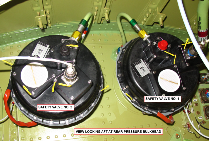
Safety Valves
There are two safety valves installed at the top of the rear pressure bulkhead at FS861.00. Each safety valve attaches to a flange on the bulkhead. The safety valves open for overpressure relief and negative pressure relief and send an open position signal to the EICAS display.
The safety valves each have a sensing device that has cabin pressure inside and static pressure outside. The sensing device moves an overpressure valve which causes the main clapper of the safety valve to open when there is a high pressure differential. The maximum positive pressure differential is 9.92 ± 0.1 psi (68.4 ± 0.7 kPa). On A/C 9002 to 9158 Post SB 700-21-034 for Global Express, or on A/C 9159 and Subs Post SB 700-1A11-21-004 for Global 5000, or on Global XRS: the maximum positive pressure differential is 10.63 ± 0.1 psi (73 ± 0.7 kPa).
When there is a negative pressure differential of 0.5 psi (3.4 kPa), the main poppet opens to release the pressure.
Except for the body, most valve parts are made from glass fiber-reinforced thermoplastics. The body is made of an aluminum casting.


Safety Valve Filters
There is one safety valve filter on each safety valve. The safety valve filter removes unwanted material from the air that goes into the sensing device in the safety valves.

01/03/17
System Operation
Definitions
Cabin Altitude:
The actual, measured, absolute cabin pressure expressed in terms of feet.
Scheduled Cabin Altitude:
The cabin altitude schedule that is internally programmed into the cabin altitude controllers.
Theoretical Cabin Altitude Schedule:
The theoretical cabin altitude schedule, programmed into the cabin pressure controllers, takes into account the aircraft maximum climb capability and the normal differential pressure. The theoretical cabin altitude schedule is designed to provide the lowest cabin altitude at the lowest possible aircraft altitude with a minimum rate of climb limit.
Automatic Mode
Two identical and independent AUTO control channels are available from the two CPCs. In AUTO mode, the cabin pressure controller controls the opening of both electrical outflow valves. The automatic controller performs the following functions:
- Automatic control of cabin altitude, regulation, and rate limitation
- Ditching sequence
- Door open protection
- Generating outputs for the EICAS display and messages
- CAIMS interface
In either AUTO mode, the cabin pressure controller controls the opening of both electrical outflow valves.
At any given time, only one AUTO system is in operation while the other AUTO system is in active standby. Smooth transfer from one AUTO system to the other automatically occurs in case of failure of the active system. It is also possible to transfer from one AUTO mode to the other through the AUTO/MANUAL switch.
During normal operation, CPC 1 is active during odd calendar days and CPC 2 is active during even calendar days.
The active cabin pressure controller drives both electrical outflow valves through the dedicated AUTO drive mechanism of the outflow valve actuator.
The active CPC assigns one of the outflow valves (OFVs) to be the master valve to control the cabin pressure. The other (slave) OFV follows at a fixed airflow ratio.
During normal operation, OFV 2 is master on day 1 and 2, and OFV 1 is master on day 3 and 4 in a 4-day cycle.
Forward and aft outflow valve (OFV) airflows are shared as follows:
| (OFV) Airflows | ||
|---|---|---|
| (FWD) Outflow Valve (OFV) (1) | (AFT) Outflow Valve (OFV) (2) | |
| Both packs ON (*) | 60% airflow | 40% airflow |
| Two packs OFF on ground (**) | Fully open | Fully open |
| One pack ON and one pack OFF in flight | Opening/closing controlled by pressure control | CLOSED |
| Two packs OFF in flight | Opening/closing controlled by pressure control | CLOSED |
(*) In this case there is one master OFV and one slave OFV. The master OFV regulates the cabin pressure. The slave OFV is commanded to follow the ratio of airflow defined in the above table. The forward and aft OFVs are alternatively slave or master according to the date of the day parity. (**) Before the throttle lever is advanced past the 20 degrees mark, which corresponds to the confirmation of the takeoff and prepressurization sequence initiation.
Automatic Primary and Secondary Modes
There are two modes of operation while the CPCS is controlled in AUTO, the primary mode with FMS and the secondary mode without FMS.
Primary Mode with FMS (Predictive)
The primary mode uses information from the FMS to minimize cabin altitude pressure rate and maximize cabin comfort. In primary mode the CPC uses time to go, time to top of climb, cruise flight level, and landing information from the FMS to compute the cabin pressurization schedule for the flight. The CPCS operates in primary mode when FMS information has been programmed, landing elevation source is selected to FMS, VNAV is the active vertical mode and the autopilot is on. In all other cases, the system defaults to secondary mode.
Secondary Mode without FMS (Reactive)
In secondary mode, the CPC uses the airplane pressure altitude and vertical speed to compute the pressurization schedule for the flight.

Automatic Prepressurization Sequence on Ground
The purpose of automatic prepressurization is to avoid cabin “bump” at takeoff.
When the LGECU indicates an airplane weight-on wheels condition and both thrust lever angles are higher than 20 degrees the prepressurization sequence is initiated. During this sequence:
- The scheduled cabin pressure is equal to the last measured cabin value (takeoff memorization) before the engine FADEC gives the “takeoff power” position
- The reference cabin pressure moves by computation towards the scheduled cabin pressure with a pressure rate limit change equal to −300 ft/min
On takeoff, cabin pressurization is controlled with a pressure rate equal to −300 ft/min limited to a differential pressure of 300 feet at sea level.

Takeoff Sequence (Abort Capability)
The purpose of this sequence is to avoid the requirement to manually reselect the landing altitude in case of an aborted flight and emergency return to the departure airport.
When the LGECU indicates the airplane is no longer weight on wheels, the automatic takeoff sequence is initiated.
When a descent rate > 500 ft/min is detected for more than 10 consecutive seconds within the first 10 minutes after T/O, the cabin pressure is scheduled at a nominal rate back to the cabin pressure of the prepressurization sequence.

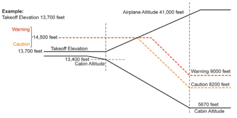
Takeoff at Field Elevation Greater than 7,230 Feet
When the airplane is in the climb, the CABIN ALT warning and caution decrease proportionally to the airplane altitude. As soon as cabin altitude reaches 7,230 feet or the airplane reaches 41,000 feet or above, the CABIN ALT caution is reset to 8,200 feet and the CABIN ALT warning is reset to 9,000 feet.

Flight Sequences with FMS (Primary Mode)
When the LGECU indicates that the airplane is in flight, the flight sequence with FMS is initiated.
This mode is in use when the following conditions are met:
- AUTOPILOT and vertical navigation are engaged
- FMS information is valid, LDG ELEV switch is set to FMS
During this sequence in climb, the scheduled cabin pressure takes the lowest value between theoretical cabin pressure and destination landing pressure −300 feet. Theoretical cabin pressure is computed from the airplane altitude cruise flight level received from the FMS.
Controller Rates – Flight Sequences with FMS
With the CPC rate at NORM, the rate of climb is limited to 500 ft/min.
With the CPC rate at HIGH, the rate of climb is automatically limited to:
- 540 ft/min, if airplane vertical speed is < 2,300 ft/min
- 800 ft/min, if airplane vertical speed is > 6,000 ft/min
- Between the above values the cabin rate of change is proportional to airplane vertical speed
- Descent – This sequence is active as long as the airplane is descending > 500 ft/min. The scheduled cabin pressure takes the lowest value between the theoretical cabin pressure and destination landing pressure −300 feet, plus barometric correction
With the CPC rate at NORM, the rate of descent is limited to 300 ft/min. With the CPC rate at HIGH, the rate of descent is automatically limited to:
- −300 ft/min if the airplane vertical speed is < 2,300 ft/min
- −800 ft/min if the airplane vertical speed is > 6,000 ft/min
- Between the above values the cabin rate of change is proportional to airplane vertical speed
Flight Sequences without FMS (Secondary Mode)
When the LGECU indicates that the airplane is in flight, the normal flight sequence is initiated (except during the takeoff sequence). During this sequence:
- Cabin pressurization is controlled with calculated rates of change according to selected landing elevation and theoretical cabin altitude schedule
- The theoretical cabin altitude schedule provides a relation between airplane altitude and theoretical cabin altitude/pressure by taking into account
- The maximum climb performance of the airplane at the minimum airplane weight
- The normal differential pressure (10.33 psid) providing a cabin altitude of 5,670 feet at 51,000 feet
The theoretical schedule is designed in order to reach the maximum differential pressure at the lowest airplane altitude, with a minimum rate of climb. The rate of change is automatic during:
- Climb – The rate of climb is directly taken from the theoretical cabin altitude schedule and the cabin rate of change is proportional to airplane vertical speed. The rate of climb will be maximized and limited to climb of 540 ft/min with CPC rate at HIGH
- The rate of climb will be limited to 500 ft/min with CPC rate at NORM
- Descent – The nominal rate of descent is limited to −300 ft/min and the rate is proportional to the airplane rate of descent. In case of high speed descent, the rate of descent is increased according to the calculation of the remaining flight time. The remaining flight time is calculated from the airplane speed received from the ADC. This increased cabin rate of change demand is automatically limited according to the airplane vertical speed, and proportional between the below values
- 300 ft/min, if airplane vertical speed is< −2,300 ft/min
- 800 ft/min, if airplane vertical speed is> −6,000 ft/min if high rate selected

The theoretical cabin altitude in the auto mode of operation of the cabin-pressure control system is as follows:
Note:
The resolution of the cabin altitude indication can be up to ±200 ft. Thus, the cabin altitude value shown on the cockpit display can be different from the value shown in the table below.
On A/C Pre SB 700-21-034 for Global Express, or on A/C 9127 to 9158 Pre SB 700-1A11-21-004 for Global 5000:
| AIRCRAFT ALTITUDE (ft) | THEORETICAL CABIN ALTITUDE (ft) | ∆P |
|---|---|---|
| -1,000 | -1,300 | 0.17 |
| -600 | 0.32 | |
| 1,000 | -526 | 0.81 |
| 2,000 | -452 | 1.27 |
| 3,000 | -378 | 1.73 |
| 4,000 | -304 | 2.17 |
| 5,000 | -224 | 2.59 |
| 6,000 | -144 | 3.00 |
| 7,000 | -64 | 3.39 |
| 8,000 | 22 | 3.77 |
| 9,000 | 103 | 4.14 |
| 10,000 | 189 | 4.49 |
| 11,000 | 411 | 4.76 |
| 12,000 | 503 | 5.09 |
| 13,000 | 601 | 5.40 |
| 14,000 | 705 | 5.69 |
| 15,000 | 809 | 5.98 |
| 16,000 | 919 | 6.25 |
| 17,000 | 1,029 | 6.51 |
| 18,000 | 1,146 | 6.76 |
| 19,000 | 1,262 | 7.00 |
| 20,000 | 1,385 | 7.22 |
| 21,000 | 1,514 | 7.44 |
| 22,000 | 1,643 | 7.64 |
| 23,000 | 1,784 | 7.83 |
| 24,000 | 1,925 | 8.01 |
| 25,000 | 2,073 | 8.18 |
| 26,000 | 2,233 | 8.33 |
| 27,000 | 2,394 | 8.48 |
| 28,000 | 2,573 | 8.61 |
| 29,000 | 2,758 | 8.72 |
| 30,000 | 2,951 | 8.83 |
| 31,000 | 3,139 | 8.94 |
| 32,000 | 3,286 | 9.05 |
| 33,000 | 3,440 | 9.16 |
| 34,000 | 3,595 | 9.26 |
| 35,000 | 3,756 | 9.35 |
| 36,000 | 3,918 | 9.44 |
| 37,000 | 4,106 | 9.50 |
| 38,000 | 4,306 | 9.56 |
| 39,000 | 4,514 | 9.60 |
| 40,000 | 4,748 | 9.62 |
| 41,000 | 4,996 | 9.64 |
| 42,000 | 5,261 | 9.64 |
| 43,000 | 5,518 | 9.64 |
| 44,000 | 5,764 | 9.64 |
| 45,000 | 6,000 | 9.64 |
| 46,000 | 6,227 | 9.64 |
| 47,000 | 6,444 | 9.64 |
| 48,000 | 6,653 | 9.64 |
| 49,000 | 6,853 | 9.64 |
| 50,000 | 7,045 | 9.64 |
| 51,000 | 7,229 | 9.64 |
Note:
The resolution of the cabin altitude indication can be up to ±200 ft. Thus, the cabin altitude value shown on the cockpit display can be different from the value shown in the table below.
On A/C 9002 to 9158 Post SB 700-21-034 for Global Express, or on A/C 9159 and Subs Post SB 700-1A11-21-004 for Global 5000, or on Global XRS:
| AIRCRAFT ALTITUDE (ft) | THEORETICAL CABIN ALTITUDE (ft) | ∆P |
|---|---|---|
| -1,000 | -1,300 | 0.18 |
| -600 | 0.32 | |
| 1,000 | -554 | 0.83 |
| 2,000 | -508 | 1.31 |
| 3,000 | -462 | 1.77 |
| 4,000 | -416 | 2.23 |
| 5,000 | -365 | 2.67 |
| 6,000 | -313 | 3.10 |
| 7,000 | -262 | 3.51 |
| 8,000 | -205 | 3.90 |
| 9,000 | -153 | 4.28 |
| 10,000 | -96 | 4.66 |
| 11,000 | 95 | 4.93 |
| 12,000 | 157 | 5.26 |
| 13,000 | 225 | 5.60 |
| 14,000 | 299 | 5.90 |
| 15,000 | 373 | 6.22 |
| 16,000 | 453 | 6.50 |
| 17,000 | 533 | 6.77 |
| 18,000 | 619 | 7.05 |
| 19,000 | 704 | 7.30 |
| 20,000 | 796 | 7.53 |
| 21,000 | 893 | 7.76 |
| 22,000 | 991 | 7.98 |
| 23,000 | 1,099 | 8.19 |
| 24,000 | 1,208 | 8.38 |
| 25,000 | 1,323 | 8.57 |
| 26,000 | 1,450 | 8.73 |
| 27,000 | 1,577 | 8.89 |
| 28,000 | 1,722 | 9.04 |
| 29,000 | 1,872 | 9.18 |
| 30,000 | 2,033 | 9.30 |
| 31,000 | 2,183 | 9.41 |
| 32,000 | 2,295 | 9.54 |
| 33,000 | 2,414 | 9.67 |
| 34,000 | 2,533 | 9.79 |
| 35,000 | 2,658 | 9.89 |
| 36,000 | 2,784 | 9.98 |
| 37,000 | 2,935 | 10.07 |
| 38,000 | 3,097 | 10.14 |
| 39,000 | 3,266 | 10.20 |
| 40,000 | 3,460 | 10.24 |
| 41,000 | 3,666 | 10.27 |
| 42,000 | 3,889 | 10.33 |
| 43,000 | 4,103 | 10.30 |
| 44,000 | 4,306 | 10.31 |
| 45,000 | 4,500 | 10.33 |
| 46,000 | 4,716 | 10.33 |
| 47,000 | 4,924 | 10.33 |
| 48,000 | 5,123 | 10.33 |
| 49,000 | 5,315 | 10.33 |
| 50,000 | 5,498 | 10.33 |
| 51,000 | 5,673 | 10.33 |


Automatic Depressurization Sequence on Ground
When the LGECU indicates an aircraft weight-on wheels condition and both throttles are at idle, the automatic depressurization sequence is initiated.
The purpose of the automatic depressurization sequence is to cancel this differential pressure on the ground. During this sequence:
- The scheduled cabin altitude is set to 15,000 ft
- The rate-corrected cabin altitude moves (by computation) towards the scheduled cabin altitude with a rate limit of change equal to 500 SL fpm for 45 seconds and then, with a rate limit of change equal to 2,000 SL fpm up to the full opening of both outflow valves
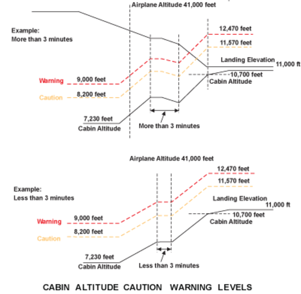
Landing Sequence at Field Elevation Greater than 5,670 Feet
This sequence does not require additional crew action if the actual landing field elevation was selected prior to takeoff. The scheduled cabin pressure is normally limited to 5,670 feet during flight and then automatically reset to the landing field elevation.
The CABIN ALT caution (cabin altitude exceeds limits) is normally set for 8,200 feet and the CABIN ALT warning is set for 9,000 feet. When the airplane altitude decreases below 41,000 feet, with landing elevation selected to 7,230 feet or higher, the CABIN ALT caution and warning start to increase proportionally to the airplane altitude. The CABIN ALT caution and CABIN ALT warning altitudes will increase 1,000 feet and 1,800 feet respectively, above the landing field elevation. Both CABIN ALT caution and warning are limited to 14,500 feet. An advisory message CAB ALT LEVEL HI is displayed on EICAS informing the crew that the warning and caution limits have been reset.


Manual Mode
In the Manual mode cabin pressure is manually controlled by the AUTO/MAN toggle switch on the Cabin Pressurization Control, directly driving both outflow valves (OFV). Each outflow valve (OFV) is driven through the Manual drive mechanism of its actuator.
The Manual mode is selected on the Cabin Pressurization Control by the AUTO/MAN toggle switch in case of failure of both AUTO modes. Selecting Manual causes the EICAS Status page to display both OFVs position indicators. In addition, analog gauge and a larger digital display replace the AUTO mode cabin rate of change digital display.
To change cabin altitude in the Manual mode the three-position, LDG ELEV UP/DN toggle switch on the Cabin Pressurization Control Panel is used. UP selection will cause the cabin altitude to climb. DN causes the cabin altitude to descend.
It is possible to fully open both OFVs in Manual mode by moving the MAN ALT toggle switch to the UP position while watching the OFV position indications.
It is also possible to fully close both OFVs in Manual mode by moving the MANALT toggle switch to the DN position while watching the OFV position indications.


The target cabin altitude in the manual mode of operation of the cabin-pressure control system is as follows:
Note:
The resolution of the cabin altitude indication can be up to ±200 ft. Thus, the cabin altitude value shown on the cockpit display can be different from the value shown in the table below.
On A/C Pre SB 700-21-034 for Global Express, or on A/C 9127 to 9158 Pre SB 700-1A11-21-004 for Global 5000:
| CRUISE FLIGHT LEVEL (ft) | TARGET CABIN ALTITUDE (ft) | TARGET ∆P |
|---|---|---|
| 18000 | 1100 | 6.75 |
| 20000 | 1400 | 7.20 |
| 22000 | 1600 | 7.65 |
| 24000 | 1900 | 8.00 |
| 26000 | 2200 | 8.35 |
| 28000 | 2600 | 8.60 |
| 29000 | 2800 | 8.70 |
| 31000 | 3100 | 8.95 |
| 33000 | 3400 | 9.15 |
| 35000 | 3800 | 9.35 |
| 37000 | 4100 | 9.50 |
| 39000 | 4500 | 9.60 |
| 41000 | 5000 | 9.60 |
| 43000 | 5500 | 9.60 |
| 45000 | 6000 | 9.60 |
| 47000 | 6400 | 9.60 |
| 49000 | 6900 | 9.60 |
| 51000 | 7200 | 9.60 |
Note:
The resolution of the cabin altitude indication can be up to ±200 ft. Thus, the cabin altitude value shown on the cockpit display can be different from the value shown in the table below.
On A/C Post SB 700-21-034 for Global Express, or on A/C 9159 and Subs Post SB 700-1A11-21-004 for Global 5000, or on Global XRS:
| CRUISE FLIGHT LEVEL (ft) | TARGET CABIN ALTITUDE (ft) | TARGET ∆P |
|---|---|---|
| 18000 | 600 | 7.05 |
| 20000 | 800 | 7.55 |
| 22000 | 1000 | 8.00 |
| 24000 | 1200 | 8.40 |
| 26000 | 1400 | 8.75 |
| 28000 | 1700 | 9.05 |
| 29000 | 1900 | 9.20 |
| 31000 | 2200 | 9.40 |
| 33000 | 2400 | 9.65 |
| 35000 | 2700 | 9.90 |
| 37000 | 2900 | 10.05 |
| 39000 | 3300 | 10.20 |
| 41000 | 3700 | 10.25 |
| 43000 | 4100 | 10.30 |
| 45000 | 4500 | 10.30 |
| 47000 | 4900 | 10.30 |
| 49000 | 5300 | 10.30 |
| 51000 | 5700 | 10.30 |
Landing Elevation
Landing elevation information is transmitted by the FMS or from the manual selection on the PRESSURIZATION panel. The value used for pressurization control by the CPCs is displayed on the STAT page.
The LDG ELEV is displayed on the STAT page when all of the following conditions are met.
- LDG ELEV FMS/MAN selector is set to FMS
- Landing destination information is programmed in the FMS
- Flight plan is activated
When the LDG ELEV FMS/MAN selector is set to MAN, the LDG ELEV selection is made from the PRESSURIZATION panel. A message is displayed on the EICAS and remains posted until an UP or DN selection is made.
To enter a new LDG ELEV, hold the UP/DN switch until the desired field elevation is reached.


System Safeties
Overpressure Relief
Overpressure relief is ensured pneumatically by each identical SFV and overrides the operation of both the AUTO and MAN mode. When maximum differential pressure is reached, an overpressure valve located on the safety valve, opens to outside pressure. The differential pressure shall not exceed 0.1 psi during taxi and takeoff and 1.0 psi upon initial landing. At 10.63 ± 0.1 psi, the safety valve opens. At 10.85 psi, the CABIN DELTA P message is displayed on the EICAS and the digital readout on the STAT page changes to red.
Negative Pressure Relief
Negative pressure relief is ensured pneumatically by each identical SFV and overrides the operation of both the AUTO and MAN mode. During an emergency descent without cabin airflow, when the outside pressure becomes slightly greater than cabin pressure, the SFV opens to control negative pressure at a value lower than or equal to −0.5 psid. A warning message is displayed on the EICAS and the digital readout on the STAT page changes to red.
Door Open Sequence
This sequence prevents cabin pressurization if the aircraft doors are not closed and fully locked. The following table summarizes the outflow valve positions.

Cabin Altitude Limitation
The cabin altitude limitation is ensured from the Manual indicator module, included in the Cabin Pressure Controller, driving the Manual channel of the electrical outflow valve. When the cabin altitude reaches 14,500 ± 500 ft, the cabin altitude limitation signal is active. This closes the outflow valve through the Manual channel of the outflow valve actuator until cabin altitude becomes lower than 14,500 ft ± 500 ft. This signal also overrides the Manual mode operation and closes the outflow valve through the Manual channel of the outflow valve actuator.
Outflow Valve Travel Limiter
An outflow valve (OFV) travel limiter device is included on each electrical OFV to limit (for differential pressure higher than 7 ± 0.5 psid) the OFV opening to a safe value (50 degrees), considering the high altitude requirements.
When the differential pressure is higher than 7 ± 0.5 psid, a finger slides inside its guide and mechanically prevents the opening of the OFV beyond 50 degrees. This function is monitored through a double position switch.
OUTFLOW VLV Close Switches
Two OUTFLOW VLV switches on the cabin pressurization control panel close the associated outflow valve (OFV).
In both AUTO modes and in manual mode, when the OUTFLOW VLV switch is selected, the associated outflow valve is directly driven (through the manual drive mechanism of its actuator) to the closed position. The controllers receive the command and provide the status to EICAS. The appropriate OUTFLOW VLV 1/2 CLSD status message will be displayed.

Safety in Case of Ditching
Safety in case of DITCHING is achieved through an automatic sequence in both AUTO modes and through a manual sequence in manual mode. Safeties ensure that the cabin is fully depressurized and then the outflow valves fully closed. The automatic sequence is generated automatically from the DITCHING switch selection:
- ECS flow is shut off
- Cabin is depressurized
- The outflow valves (OFV) are driven to the closed position
The automatic ditching sequence is inhibited above 15,000 ft.
When the DITCHING function is selected, the EICAS displays FWD and AFT outflow valves (OFV) position indications.
The manual ditching sequence is manually controlled by the crew through the following commands:
- ECS flow is selected off
- Cabin is depressurized by selecting the EMERG DEPRESS switch
- The outflow valves (OFV) are driven to the closed position by selecting both OUTFLOW VLV switches
The controller provides a status of the position of the DITCHING switch in all modes. In this case, the DITCHING ON status message will be displayed.
Emergency Depressurization (Dump)
Rapid cabin depressurization (Dump function) is available in both AUTO and MANUAL mode.
When the EMER DEPRESS switch is selected, a rapid depressurization is performed by the opening of both OFVs directly through the manual drive mechanism of each actuator. The controllers provide the status to EICAS. The EMER DEPRESS caution message will be displayed.
The cabin altitude limitation function overrides the Emergency Depressurization function. When EMERG DEPRESS function is selected, EICAS provides FWD and AFT OFV position indications.
Emergency Depressurization
When the EMERG DEPRESS switch is selected ON, a fast depressurization is performed in AUTO or MAN mode by commanding both OFVs to open.
Cabin altitude limitation functions override this function and does not allow the cabin altitude above 14,500 ± 500 feet. The cabin rate of climb limitation is inoperative during the emergency depressurization mode of operation.


Automatic Emergency Descent Mode (SB: 700-22-003 or 700-1A11-22-001)
The automatic emergency descent mode (EDM) is used to initiate an autopilot-controlled descent in the event the flight crew has become incapacitated due to loss of cabin pressure. The mode is automatically enabled if the autopilot is engaged,the aircraft altitude is above 25,000 feet and the cabin altitude has exceeded 14,500 feet. The mode may only be canceled by disconnecting the autopilot.
Once enabled, an EICAS warning message of EMERGENCY DESCENT is displayed and an aural message of EMERGENCY DESCENT is heard.
The flight director enters the heading select (HDG) and flight level change (FLC) modes in order to capture a preselected altitude of 15,000 feet (4,500 meters) and a heading that is 90 degrees left of the aircraft’s current heading. EDM is displayed in red on the vertical mode column of the FD annunciator while HDG is displayed in green on the lateral mode column. The heading and preselect altitude may be changed by the flight crew while remaining in EDM.
The autothrottle system is automatically engaged when EDM is enabled. The autothrottle remains engaged until pilot selection of the autothrottle disengage switches. It will not disengage when the EDM mode is disabled by autopilot disconnect.
During the EDM-initiated descent the airspeed target is synchronized to Vmo −10. The EDM speed bug is displayed in red adjacent to the airspeed target, however, the speed knob is inoperative while EDM is active.
The flight director performs a normal transition to ASEL and ALT mode at 15,000 feet with an airspeed target of 250 kt being set at ASEL.
The emergency descent mode may only be canceled by disconnecting the autopilot. Once the AP is disengaged, the flight director will remain in the lateral and vertical modes that were active when EDM was enabled. For example, if the AP is disengaged while in the descent, HDG and FLC will remain the active modes as it provides guidance to the preselect altitude value of 15,000 feet.
08/22/19
System Monitoring
Failure monitoring is performed by different built-in-tests (BITE). System monitoring includes both AUTO mode monitoring, the Manual mode monitoring,both Cabin Altitude Limitation monitoring, both outflow valve (OFV), Travel Limiter monitoring, and both Safety Valve position monitoring.
Failure information of the AFT (or FWD) outflow valve (OFV) is transmitted from the outflow valve (OFV) to the Cabin Pressure Controller 1 (or 2) through the RS 422 connection(to be transmitted to the EICAS and/or CAIMS).
In case of detected failure, the following actions are performed totally or partially according to the failure criticality:
- A message is sent to the EICAS and/or CAIMS
- Safe/corrective action on the outflow valve (OFV) command
- Safe overriding action to maintain the outflow valve (OFV) position
- Smooth transfer from selected AUTO mode to the other
- EEPROM failure storage
Power-On Built-In Test
The power-on built-in test (PBIT) checks functions and/or components of the system, including the manual mode and both cabin altitude limitations, which can’t be tested during continuous monitoring. The test is automatically initiated from each cabin pressure controller at aircraft power on,when the AUTO mode is selected.
Continuous Built-In Test
In both AUTO systems, system continuous monitoring is performed from the cabin pressure controller and both outflow valves (OFVs).


System Test
Initiated Built-In Test – CAIMS
The cabin pressure controllers can be tested via CAIMS. If the system passes the test, a "Test Results: Pass" message will be displayed (on the PMAT). If a failure occurs the appropriate CAIMS report will be generated, and for certain failure conditions, a CAS message will also be generated. The CAIMS report will identify the failed unit.
The cabin pressure control system status is displayed in the "System Diagnostics/LRU Test" pages on the CAIMS PMAT. The data is real time, meaning that it will display current operating parameters. This data is presented in "userfriendly" terms, such as temperature in °C, pressure in psig, position of switches and components, rather than digital codes. Control panel switch inputs are displayed as well as outflow valve positions. Travel limiter status and cabin pressure controller temperature and pressure signals are also displayed.

System Indication
The Cabin Pressurization system status is displayed on the EICAS primary page and the EICAS Status page.
The following table provides details of the items displayed on the EICAS Status page:
| EICAS Status Page | |||||
|---|---|---|---|---|---|
| ITEM | GREEN | RED | AMBER | MAGENTA | CYAN |
| Cabin Altitude (Range: −1,000 to +15,000 feet) | Normal value | Cabin altitude >+9,000 ft | Cabin altitude >+8,200 ft and >+9,000 ft amber dashes if no valid data | --- | --- |
| Cabin Vertical Speed (Range: −2,000 to +2,000 fpm) | Digital value with vertical arrow in auto mode. In Manual mode normal value replaced with analog gauge and larger digital display. | --- | Cabin rate >+2,000 fpm or <−2,000 fpm. Amber dashes if no valid data | --- | |
| Differential Pressure (Range: −5 to +11 PSID) | Normal pressure | Value >+9.92 psid or <−0.4 psid | Cabin rate is: >+2,000 fpm or <−2,000 fpm. Amber dashes if no valid data | --- | --- |
| Landing Elevation (Range: −1,000 to +15,000 ft in 10-ft increments). See note below | --- | --- | Amber dashes if no valid data | Data from FMS | Data set by crew using LDG ELEV UP/DN toggle switch |
| FWD and AFT outflow valve position (Position indicated as percentage: 0% = full closed 100% = full open Scaled in 3 zones: 1st half = 0 to 25% 3rd qtr = 25 to 50% 4th qtr = 50 to 100% | Green needle displayed in AUTO mode if: a) Either or both OUTFLOW VLV PBAs are selected - only the outflow valve(s) selected is (are) displayed or b) EMER DEPRESS PBA is selected - both outflow valve positions are displayed or c) DITCHING PBA is selected - both outflow valve positions are displayed. Displayed continuously in Manual mode. | --- | --- | --- | --- |
Note:
Landing Elevation is not displayed in Manual mode.

08/20/20
Component Location Index
| Component Location Index | |||
|---|---|---|---|
| IDENT | DESCRIPTION | LOCATION | IPC REF |
| A21/A22 | CABIN PRESSURE CONTROLLER | ZONE(S) 230 | 21-31-01 [ GX ] [ GXRS ] [ G5000 ] |
| L8/L9 | OUTFLOW VALVES | ZONE(S) 230/250 | 21-31-05 [ GX ] [ GXRS ] [ G5000 ] |
| L10/L11 | SAFETY VALVES | ZONE(S) 250 | 21-31-09 [ GX ] [ GXRS ] [ G5000 ] |
| - | SAFETY VALVE FILTERS | ZONE(S) 250 | 21-31-11 [ GX ] [ GXRS ] [ G5000 ] |
| AP9 | PRESSURIZATION CONTROL PANEL | ZONE(S) 220 | 21-31-13 [ GX ] [ GXRS ] [ G5000 ] |