06/03/16
Overview
The power plant oil system consists of a lubrication system, an oil replenishment system, and an engine drain system. The lubrication system lubricates, cools, and cleans the engine bearings and gears. Oil also supplies a squeeze film to the bearings. The oil decreases the temperature and keeps the wear of the components to a minimum. The system is a full flow recirculating type.
The oil replenishment system permits refilling of the oil tank of each engine and the APU individually when on the ground. The engine drain system collects and discharges overboard all unwanted fluids from a variety of points in the engine.
Lubrication System
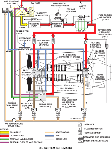
The oil for the engine is stored in a main tank (reservoir) and an auxiliary tank, both are an integral part of the accessory gearbox. A single element pressure pump takes oil from the tank to supply the front bearing chamber (FBC), the rear bearing chamber (RBC) and the accessory gearbox, via an oil pressure filter and a fuel cooled oil cooler (FCOC).
A four element scavenge pump removes the scavenge oil from the front and rear bearing chambers, the accessory gearbox and the centrifugal breather, and returns it to the tank in a common return line. The pressure pump and scavenge pumps are integrated into the oil pumping unit, mounted at the rear of the accessory gearbox.
The bearing chambers, accessory gearbox and oil tank are all vented via an air/oil separator (breather) in the gearbox. Magnetic chip detectors are fitted on three of the scavenge lines to monitor the internal condition of oil lubricated components in the system.