


12/08/17
Overview
The distribution system supplies the pressurized areas of the aircraft with temperature controlled and conditioned air. Two air conditioning units supply the conditioned air to the distribution system. The distribution system includes the distribution ducts that go to the flight compartment and the forward and aft passenger compartment.
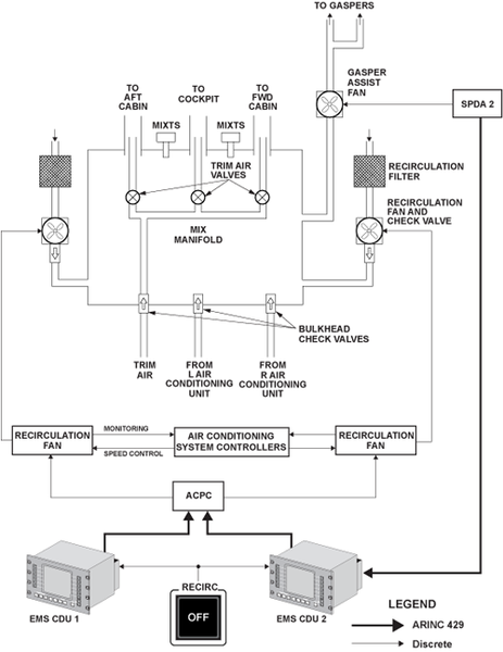
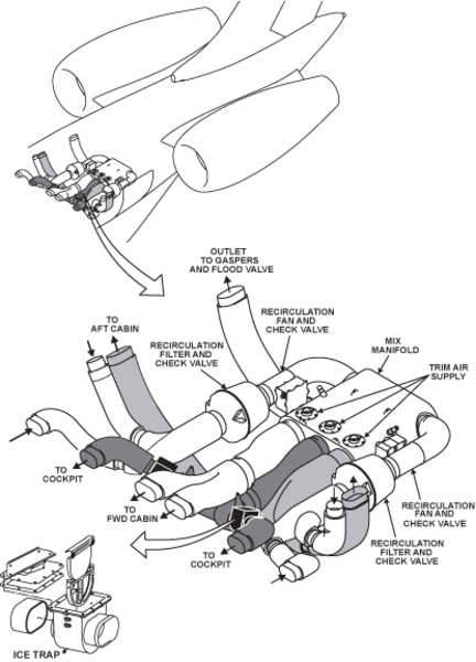
The airflow from the left and right air conditioning units goes to the mix manifold through their related bulkhead check valve. The left and right airflows are mixed in the mix manifold. The conditioned air from the mix manifold is supplied, through the low-pressure ducts, to the flight compartment and the forward and the aft passenger compartments.
The flight compartment distribution uses gaspers to give the flight crew cool air. Exhaust ducts are used to remove the air from the flight compartment. This keeps constant airflow through the flight compartment.
The forward and aft passenger compartments use gaspers to give the passengers cool air. Exhaust ducts are used to remove air from the forward and aft passenger compartments. This keeps constant airflow through the forward and aft passenger compartments.
The Recirculation System has a mix manifold that takes the air from the two air conditioning units and mixes it with air from the recirculation fans. The air then goes through one of three outlets to the pressurized zones of the aircraft. The recirculation fans pull the air from the forward and aft passenger compartments. Recirculation filters clean the air before it goes through the fan and into the mix manifold.
The air conditioning system controllers control the recirculation fans. Mix manifold temperature sensors supply the air conditioning system controllers with an indication of the temperature of the air in the mix manifold. Bulkhead check valves stop the flow of air in the reverse direction if an air conditioning unit is not in operation.
04/21/16
Internal Distribution System
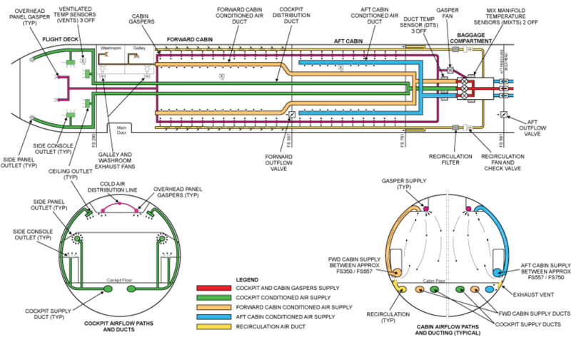
The internal distribution system controls the temperature and flow of air from the air conditioning units and the recirculation system to the aircraft pressurized areas. The airflow from the left and right air conditioning units goes to the mix manifold through their separate bulkhead check valves. The recirculation air comes from the exhaust ducts in the passenger compartments and goes to the mix manifold through the recirculation fan filters. The airflow from the left and right air conditioning units and the recirculation air are mixed together in the mix manifold. The mix manifold supplies the conditioned air through the low pressure ducts to the flight compartment and the forward and the aft passenger compartments. The outlets in the center of the mix manifold give more fresh airflow to the flight compartment and the gasper lines.
On A/C 9357 and Subs and Post SB 700-21-035 for Global Express/XRS, or 9353, 9356 and Subs and Post SB 700-1A11-21-005 for Global 5000, two ice filters prevent ice pellets from entering the passenger compartment ducts.
The flight compartment distribution uses gaspers, vents and console outlets to supply the flight crew with cool air. Exhaust ducts remove the air from the flight compartment. This keeps a constant airflow through the flight compartment. The forward and aft passenger compartments use gaspers and special panels to supply the passengers with cool air. Exhaust ducts remove air from the forward and aft passenger compartments. This keeps a constant airflow through the forward and aft cabin.
The bleed-air control panel, installed on the overhead panel in the flight compartment, controls the operation of the internal distribution system.

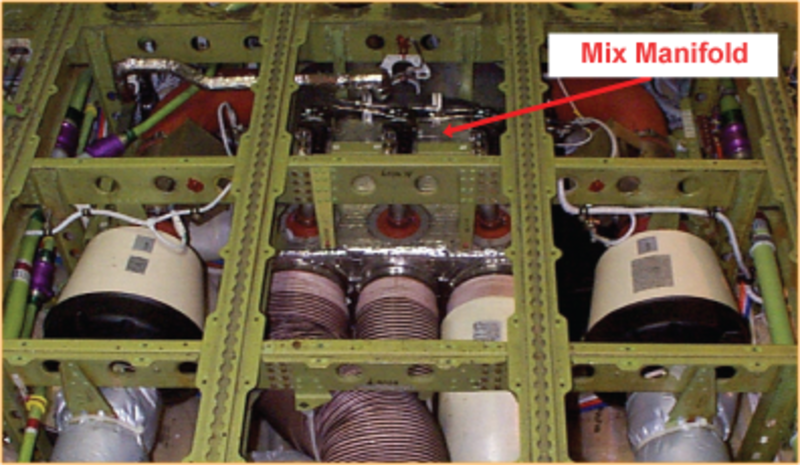
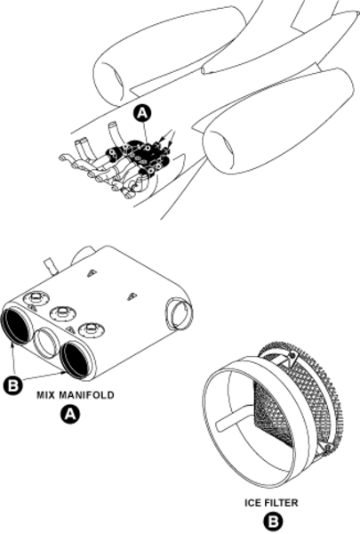
Mix Manifold
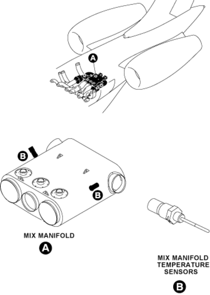
The mix manifold is installed in the aft power distribution/ECS compartment. The mix manifold mixes the air from the air conditioning units with the recirculated air from the forward and aft passenger compartments.
The mix manifold is manufactured from glass/carbon fiber and reinforced with phenolic resin, and is covered with a 0.5 inch flame resistant insulation layer to prevent water condensation on the outside walls of the manifold. The condensed water inside the manifold is collected at a drain port. and left hand sides of the manifold. The recirculated air inlets are designed so that a layer of warm air protects the wall of the unit from ice build up.
Mix Manifold Temperature-Sensors
The mix manifold temperature-sensors each have two sensing elements in the same casing. The resistance of the sensing elements decreases as the temperature increases and increases as the temperature decreases. The air conditioning system controllers monitor the resistance of the sensing elements to find the temperature of the mix manifold.
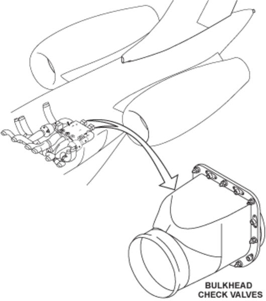
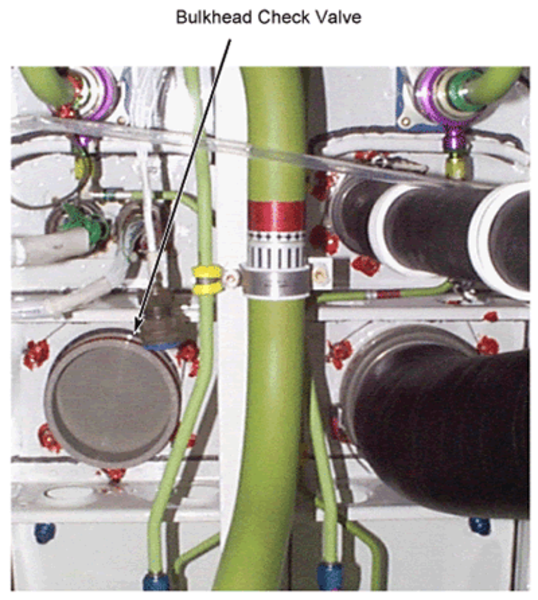
Bulkhead Check Valves
The bulkhead check valves are installed in the rear pressure bulkhead at FS861.00. The check valves allow the airflow from the air conditioning units to the mix manifold, and stops reverse airflow from the mix manifold to the air conditioning units when the packs are not in operation. There is one bulkhead check valve for each air conditioning unit.
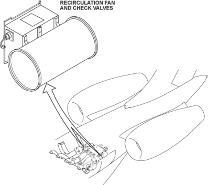
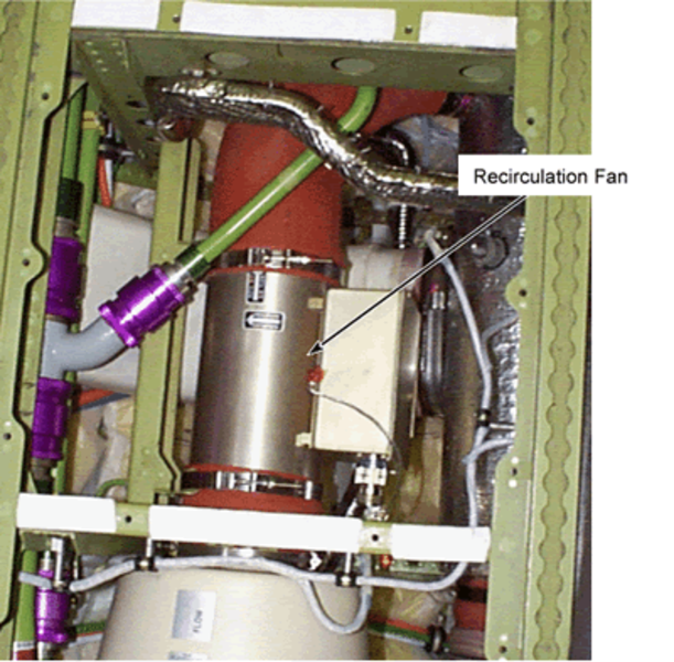
Recirculation Fan and Check Valve (RFAN)
The recirculation fans (RFAN) are installed in the aft power distribution/ECS compartment. The recirculation fans remove the air from the pressurized compartments of the aircraft through the recirculation ducts. The air then goes to the mix manifold through the recirculation filter. The check valve at the fan outlet stops reverse flow of air from the mix manifold to the cabin if the fan is unserviceable.
The recirculation system operates automatically when one of the air conditioning units is in operation. The fan starts at a high speed. The air conditioning system controller then decreases the speed of the fan as necessary. The recirculation fans get electrical power from the ACPC. The recirculation fan gets an input from the air conditioning system controller. This input changes the speed of the fan. When the RECIRC switch/light on the bleed-air control panel is set to OFF, the recirculation fans stop.
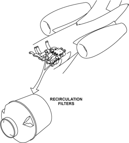
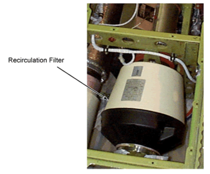
Recirculation Filter
The recirculation filters are installed in the aft power distribution/ECS compartment at the inlet of the recirculation fans. The filters clean the air before it enters the distribution system.
The recirculation fans move the air from the cabin to the mix manifold through the recirculation filters. As the air flows through the filters, small particles are caught in the material inside the filters. The recirculation filter is a replaceable cartridge filter.
Ice Filters
(On A/C 9357 and Subs and Post SB 700-21-035 for Global Express/XRS, or 9353, 9356 and Subs and Post SB 700-1A11-21-005 for Global 5000)
The ice filters are installed on the mix manifold, upstream of the two passenger-compartment duct outlets. They prevent ice pellets from entering the passenger compartment ducts.
Drain Mast
The drain mast is the outlet port for the aircraft that drains flammable residual fluids (oil, fuel and water) through a controlled drainage path to the ambient air. The drain mast is located below the aircraft fuselage from FS861.00 to FS877.25. The fluids tend to collect in different components of the engines, the fuel, the oil and the hydraulic systems.

Global Express
Global XRS
Global 5000
Distribution Ducting
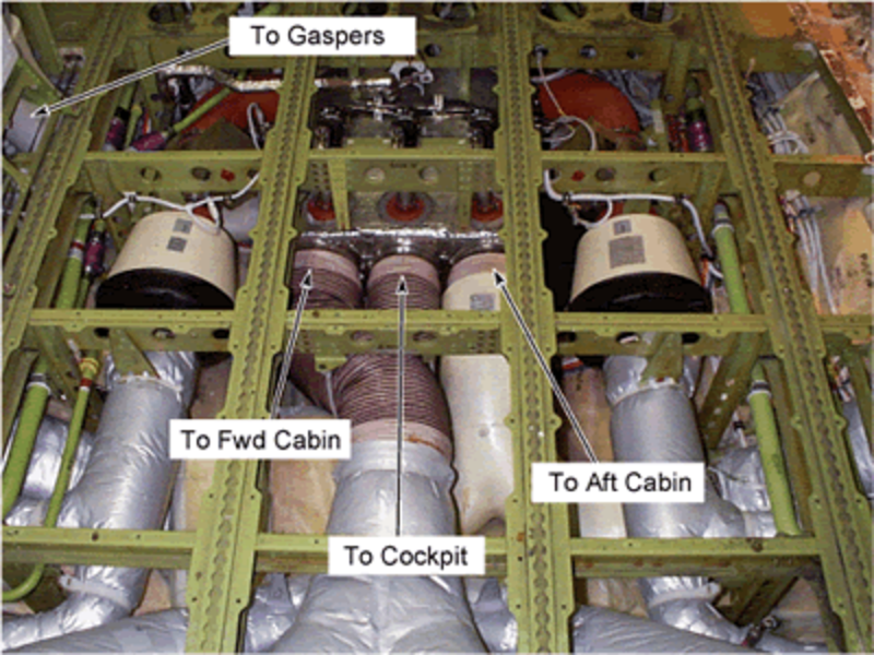
The distribution ducting to the aft cabin zone supplies air through two ducts inside the dado panels along the aft cabin sidewalls. This air is supplied above the windows or above the luggage compartments, depending on the completion center configuration.
The distribution ducting to the forward Cabin zone is routed under the floor and then inside the dado panels along the side wall. The distribution ducting to the cockpit supplies the air first by routing under the floor and then to the side panels and to the side console outlets and to the top of bulkhead 280 on both sides of the cockpit.
The gasper line supplies air, which is colder than the distribution system, along the topside of the cabin and thus to the individual outlets in the flight deck and the cabin zones.
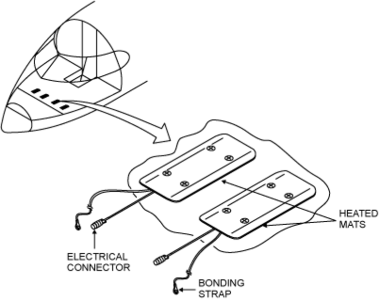
Pilot Heated Mats
Electrical heaters are used to heat the pilot and copilot's feet. They consist of electrical heating elements in a mat. There are two heated mats; one for each foot, fixed on the cockpit floor under the kick plates. Each heater dissipates approximately 70 Watts. The temperature of the kick plates is maintained between 65 °F and 75 °F (18 °C and 23 °C).
A safety thermal switch is installed in each heater to cut off electrical power if kick plate temperature exceeds 150 °F (65 °C). The heaters will again operate when the temperature falls below the trip point. Although normally on, the pilot and copilot foot heaters can be switched off independently through the CNTL mode of the EMS CDU.
04/05/22
Ventilation System
The ventilation system is used to supply a good flow of air to the flight compartment and to the passenger compartment.
The ventilation system lets the cold air, conditioned air and the recirculation air flow through the pressurized fuselage. It also moves the warm air out of the avionics compartment and from behind the electronic displays. It is made of low pressure ducts, vents and gaspers.
The ventilation system supplies cold air to the gaspers on the overhead panel and to the air vents on the bulkhead top panels in the flight compartment. The system removes the exhaust air, and moves a part of this air to the passenger compartment. The system also removes the exhaust air from the area that follows:
- Forward Fuselage Equipment-Compartment
The ventilation system also removes the exhaust air from the back of the displays in the flight compartment. If the two air conditioning systems fail and there is some smoke in the aircraft, the emergency air is supplied through the emergency ram-air duct.
Flight Compartment Gaspers
On A/C 9002 to 9139 for Global Express:
The gaspers supply cold air controlled at a temperature lower than the passenger compartment temperature to the flight crew. The gaspers are installed on the left side and the right side of the overhead panel and on the side panels. The control of the quantity of cold air supplied through the gaspers is independent for the left side and the right side.
On A/C 9140 to 9158 for Global Express, G5000 and GXRS:
The gaspers supply cold air controlled at a temperature lower than the passenger compartment temperature to the flight crew. The gaspers are installed on the left side and the right side of the overhead panel and on the side panels and one gasper installed on the headliner. The control of the quantity of cold air supplied through the gaspers is independent for the left side and the right side.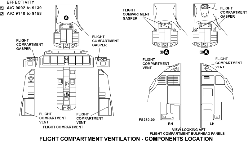
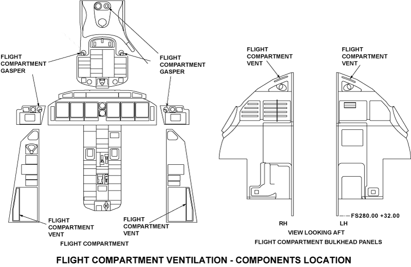
Flight Compartment Vents
The flight compartment vents supply the cold air and the conditioned air to the flight compartment. The vents for the conditioned air are installed on the left side and the right side consoles. The vents for the cold air are installed on the bulkhead top panels. The grids installed on the vents on the left side and right side consoles help keep the ducts clean.
Flight Compartment Ducts
The flight compartment ducts are installed on the structure behind the bulkhead panels. They connect to the passenger compartment ducts. They connect to each gasper on the overhead panel, and to the cold air vents on the bulkhead top panels.
The avionics cooling ducts move the warm air out from behind the avionics displays. The ducts are found behind the left side of the flight compartment behind the instrument panel and connect to the passenger compartment ducts.
Passenger Compartment Ducts
The passenger compartment ducts are found in the forward and aft areas of the passenger compartment. The ducts supply air to their related area of the passenger compartment.
The avionics cooling system includes the avionics exhaust fan. The fan is installed at the end of the avionics cooling ducts in the forward fuselage equipment compartment. The fan makes the exhaust air go through the outflow valve of the passenger-compartment pressure-control system. This valve moves the exhaust air to the aft passenger compartment.
Baggage Compartment Ducts
The baggage compartment ducts are found below the floor of the baggage compartment. These ducts connect to the mix manifold and to the ducts for the cold air, conditioned air, and recirculation air through the passenger compartment bulkhead and through the floor of the baggage compartment.
These ducts also include the exhaust air ducts. They collect the exhaust air found below and above the floor of the passenger compartment and move it to the mix manifold through the recirculation fan.
Entry Area Exhaust Fan
The primary purpose of the entry area exhaust fan is to remove the cold air from behind the acoustical curtain. It is installed in the avionics bay. On Global XRS/5000, the electrical power is provided by the DCPDE 1 from the cabin DC bus 1. On Global Express, the electrical power is provided by the DC TRU CABIN FEED bus. The unit is controlled using the galley Touch Screen Equipment (TSE). The default state of the unit at power up is OFF. A fuse rated 0.5 A is installed adjacent to the fan unit for over current protection.
G5:

GX and XRS:

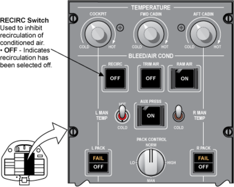
Control Panel
The air conditioning panel is located overhead in the cockpit. It contains a RECIRC switch to control the recirculation fans.
08/21/24
System Operation
The air conditioning system controller (ACSC) controls the recirculation and mixing manifold temperature.
Recirculation Fan

During usual operation, the ratio of the airflow from the mix manifold is approximately 50 percent recirculated air and 50 percent air from the air conditioning units. During maximum heating or cooling operation, the ratio of the recirculated air is increased to approximately 66 percent and air from the air conditioning units is decreased to approximately 34 percent.
Three supply ducts take the mixed air from the mix manifold to the flight compartment and the forward and aft passenger compartments. The airflow from the mix manifold to the forward and aft passenger compartments is approximately 78 percent of the total airflow from the mix manifold. The airflow to the flight compartment is approximately 22 percent.
The recirculation fans are automatically ON when the power supply is available. The Mixing and Recirculation System operates automatically when at least one pack is switched ON. The ACSC controls the fan speed in accordance with the mixing manifold temperature control law. Thus, the fan speed depends on the pack flow demand, and on the mixing manifold temperature if the associated cooling pack is operating.
If one pack is OFF, the associated recirculation fan is switched automatically to its minimum speed.
In case of smoke in the cabin or other problems, the recirculation fans can be switched off manually by operating the "RECIRC" pushbutton. In case of a failure detected by the speed control unit, it stops automatically, shuts off the fan power supply to the fan and will attempt a restart of the fan. When the recirculation fan is detected as failed by the fan speed control unit, a discrete input is sent to the ACSC. The ACSC sends an advisory message RECIRC FAN FAIL to EICAS if either or both fans fail.
System Indication
Distribution and Recirculation System Synoptic
The distribution and recirculation system synoptic is part of the air conditioning synoptic:
| Item | Green | Amber | White | Magenta | Cyan |
|---|---|---|---|---|---|
| - - - | - - - | RECIRC OFF | - - - | RECIRC FAIL | |
| Mixing Manifold | When recirculation fan is off | message when recirculation fans have failed |
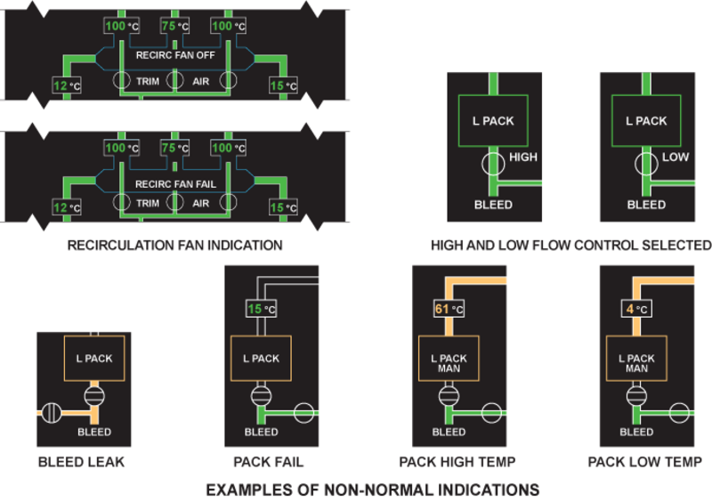
Air Conditioning Synoptic Page
The following represents the normal and examples of non-normal indications shown on the air conditioning synoptic page:

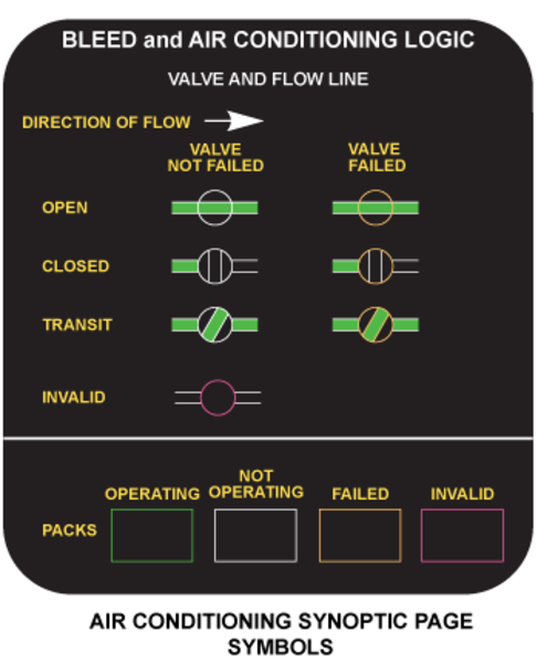
Air Conditioning Synoptic Symbols
The following represents the EICAS symbols and flow line logic for the air conditioning synoptic page. The symbols are shown in serviceable and failed conditions.
System Test
Initiated Built-In Test - CAIMS
The air conditioning system controllers can be tested via CAIMS. The following logic applies:
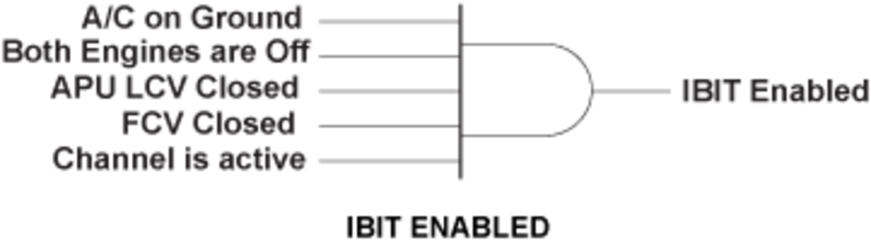
During initiated built-in test (IBIT), the following items on each channel are tested:
- Internal test (EPROM, RAM, EEPROM, WATCHDOG, RS-422 and ARINC)
- FCV pneumatic valve test (check FCV is in closed position)
- HASOV open/full close test
- TCV, TAV, FLV speed test
- Input tests
If a failure occurs, the continuous built-in test (CBIT), which is continuously operating, will detect and report the failure; a CAIMS message will be generated, and for certain failure conditions, a CAS message will also be generated.Should a sensor or valve fail, the appropriate CAIMS message will be generated, identifying the failed unit. If the failure has occurred within the ACSC, a generic CAIMS message will be generated.
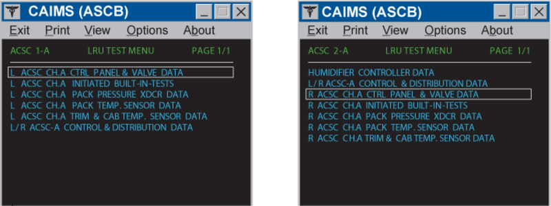
CAIMS Display Data
The air conditioning system status is displayed in the “System Diagnostics/LRU Test” pages on the CAIMS PMAT.
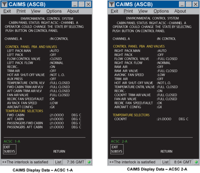
The data is real-time, meaning that it will display current operating parameters. This data is presented in “user-friendly” terms, such as temperature in °C, pressure in PSIG, position of switches and components, rather than digital codes.
Pack temperatures that are displayed are:
- Pack inlet temperature
- Compressor discharge temperature
- Water extractor temperature
- Pack discharge temperature
- Mix manifold temperature
Switch positions are displayed as well as valve positions for:
- Flow control valves
- Ram air valve
- Hot air shutoff valves
- Trim air valves
- Temperature control valves
- Fan air valves
Pressures that are displayed are:
- Pack inlet pressure
- Pack flow differential pressure
- Pack anti-ice pressure
Measured pack flow is displayed in lb/min. For each zone, duct temperature and ventilated sensor temperature are also displayed.
08/24/20
Component Location Index
| Component Location Index | |||
|---|---|---|---|
| IDENT | DESCRIPTION | LOCATION | IPC REF |
| - | MIX MANIFOLD | ZONE(S) 171/172 | 21-21-05 [ GX ] [ GXRS ] [ G5000 ] |
| - | ICE FILTER | ZONE(S) 171/172 | 21-21-05 [ GX ] [ GXRS ] [ G5000 ] |
| E24/E30 | MIX MANIFOLD TEMPERATURE SENSOR | ZONE(S) 171/172 | 21-21-09 [ GX ] [ GXRS ] [ G5000 ] |
| - | BULKHEAD CHECK VALVE | ZONE(S) 171/172 | 21-21-17 [ GX ] [ GXRS ] [ G5000 ] |
| B17/B21 | RECIRCULATION FAN AND CHECK VALVE | ZONE(S) 171/172 | 21-21-21 [ GX ] [ GXRS ] [ G5000 ] |
| - | RECIRCULATION FILTER | ZONE(S) 171/172 | 21-21-25 [ GX ] [ GXRS ] [ G5000 ] |
| - | FLIGHT COMPARTMENT GASPERS | ZONE(S) 221/222 | 21-22-01 [ GX ] [ GXRS ] [ G5000 ] |
| - | FLIGHT COMPARTMENT VENTS | ZONE(S) 221/222 | 21-22-05 [ GX ] [ GXRS ] [ G5000 ] |
| - | FLIGHT COMPARTMENT DUCTS | ZONE(S) 221/222 | 21-22-09 [ GX ] [ GXRS ] [ G5000 ] |
| - |
PASSENGER COMPARTMENT DUCTS |
ZONE(S) 141/142 ZONE(S) 151/152 ZONE(S) 161/162 ZONE(S) 231/232 ZONE(S) 241/242 |
21-22-21 [ GX ] [ GXRS ] [ G5000 ] |
| - | BAGGAGE COMPARTMENT DUCTS | ZONE(S) 171/172 | 21-22-25 [ GX ] [ GXRS ] [ G5000 ] |
| B650 | ENTRY AREA EXHAUST FAN | ZONE(S) 141 | 21-22-37 [ GX ] [ GXRS ] [ G5000 ] |